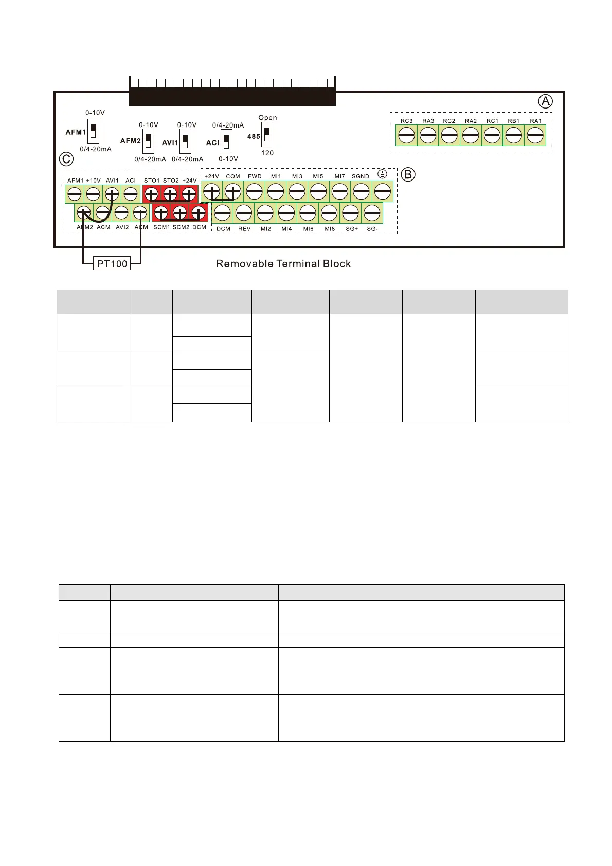
Chapter 6 Control TerminalsCP2000
6-8
6-2 Specifications of Control Terminal
Terminal
function
Group Conductor
Stripping
length [mm]
Max. wire
gauge
Min. wire
gauge
Torque (±10%)
Relay
Ⓐ
Solid
4–5
1.5 mm
2
[16 AWG]
0.2 mm
2
[26 AWG]
5 kg-cm
[4.3 lb-in]
[0.49 Nm]
Strand
Control
board
Ⓑ
Solid
6–7
8 kg-cm
[6.9 lb-in]
[0.78 Nm]
Strand
Control
board
Ⓒ
Solid
2 kg-cm
[1.7 lb-in]
[0.20 Nm]
Strand
Wiring precautions:
In the figure above, the default for STO1, STO2, +24V and SCM1, SCM2, DCM are short circuit.
The +24V from section Ⓒ of above figure is for STO only, and cannot be used for other
purposes. The default for +24V-COM is short circuit and SINK mode (NPN); please refer to
Section 4 Wiring for more detail.
Tighten the wiring with slotted screwdriver:
Ⓐ Ⓑ is 3.5 mm (wide) x 0.6 mm (thick); Ⓒ is 2.5 mm (wide) x 0.4 mm (thick)
When wiring bare wires, make sure they are perfectly arranged to go through the wiring holes.
Terminals Terminal Function Default (NPN mode)
+24V
Digital control signal common
(Source)
+24V 5% 200mA
COM Digital control signal common (Sink) Common for multi-function input terminals
FWD Forward-Stop command
FWD-DCM:
ON
forward running
OFF
deceleration to stop
REV Reverse-Stop command
REV-DCM:
ON
reverse running
OFF
deceleration to stop
Figure 6-14
 Loading...