ASDA-A2 Chapter 4 Panel Display and Operation
4-6 Revision February, 2017
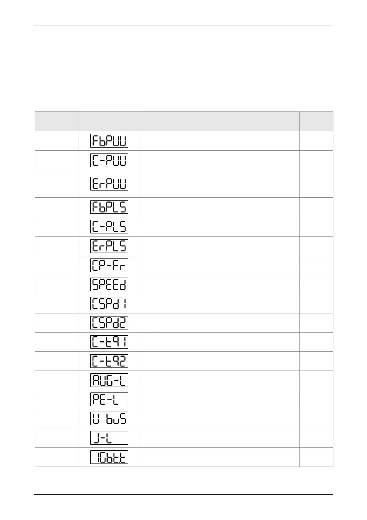
4.3.5 Monitor Display
When the drive is applied to the power, the display will show the monitor displayed symbol for a
second, and then enter into the Monitor Mode. In Monitor Mode, the UP / DOWN Key can change
the desired monitor variable. Or, the user can directly change parameter P0-02 to set the monitor
code. When applying to the power, the system will pre-set the monitor code according to the
setting value of P0-02. For example, the setting value of P0-02 is 4. Every time when applying to
the power, it will display C-PLS monitor sign first, and then shows the input pulse number of pulse
command.
P0-02 Setting
Value
Monitor Displayed
Symbol
Description Unit
0
Motor feedback pulse number (after the scaling of
electronic gear ratio) (User unit)
[user unit]
1
Input pulse number of pulse command (after the
scaling of electronic gear ratio) (User unit)
[user unit]
2
The difference of error pulse number between
control command pulse and feedback pulse number
(User unit)
[user unit]
3
Motor feedback pulse number (encoder unit) (1.28
millions Pulse/rev)
[pulse]
4
Input pulse number of pulse command (before the
scaling of electronic gear ratio) (encoder unit)
[pulse]
5
Error pulse number (after the scaling of electronic
gear ratio) (encoder unit)
[pulse]
6
Input frequency of pulse command [Kpps]
7
Motor speed [r/min]
8
Speed input command [Volt]
9
Speed input command [r/min]
10
Torque input command [Volt]
11
Torque input command [%]
12
Average torque [%]
13
Peak torque [%]
14
Main circuit voltage [Volt]
15
Load / Motor inertia ratio (Note: If it shows 13.0, it
means the actual inertia is 13)
[1 times]
16
IGBT temperature
[℃]
 Loading...


