Chapter 8 Parameters ASDA-A2
8-42 Revision February, 2017
High-speed pulse input
Logic
Pulse
Type
Forward Reverse
0
Positive Logic
Pulse +
Symbol
Sign = high Sign = low
Low-speed pulse input
Logic
Pulse
Type
Forward Reverse
0
Positive
Lo
ic
Pulse +
Symbol
Sign = low Sign = high
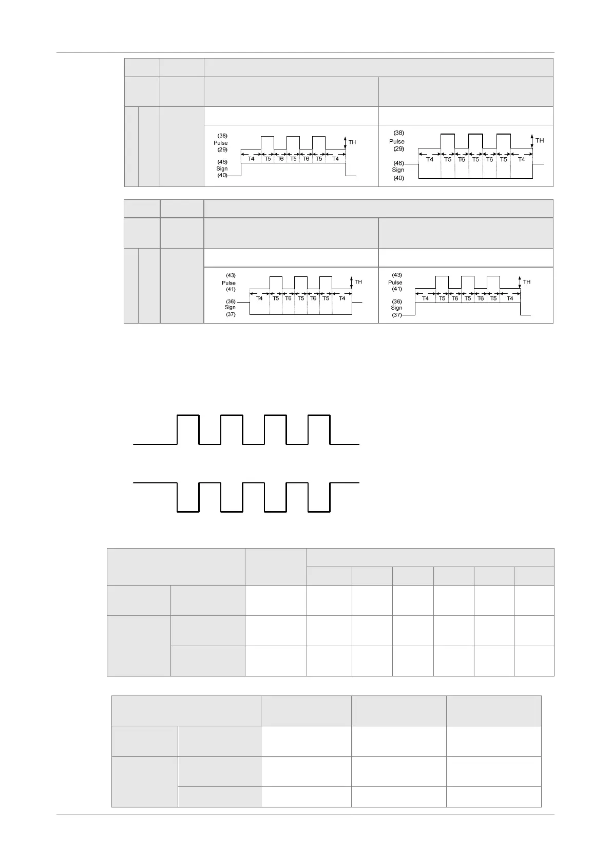
For digital circuit, it uses 0 and 1 represents two status, which is high voltage and low
voltage. In Positive Logic, 1 represents high voltage and 0 represents low voltage
and vice versa in Negative Logic.
For example:
Positive Logic
Negative Logic
Pulse
Specification
Max. Input
Frequency
Minimum time width
T1 T2 T3 T4 T5 T6
High-speed
pulse
Differential
Signal
4Mpps 62.5ns 125ns 250ns 200ns 125ns 125ns
Low-speed
pulse
Differential
Signal
500Kpps 0.5μs 1μs 2μs 2μs 1μs 1μs
Open-
collector
200Kpps 1.25μs 2.5μs 5μs 5μs 2.5μs 2.5μs
Pulse Specification
Max. Input
Frequency
Voltage
Specification
Forward Current
High-speed
pulse
Differential
Signal
4Mpps 5V < 25mA
Low-speed
pulse
Differential
Signal
500Kpps 2.8V ~ 3.7V < 25mA
Open-collector 200Kpps 24V (Max.) < 25mA
 Loading...


