11
Quick installation guide for RPI M15A M20A inverters
O NO FF
AC O UTPUT RS485 DC SWITCH DC INPUT
DC1 DC2
O FF
O N
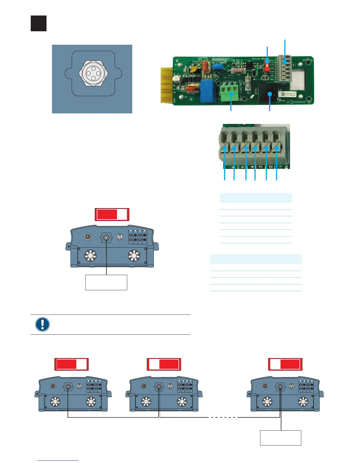
Connecting to a datalogger via RS485 (optional)
9
Pin Designation
1 VCC(+12V)
2 GND
3 DATA+
4 DATA–
5 DATA+
6 DATA–
RS485
Data format
Baud rate 9600, 19200, 38400
Databits 8
Stopbit 1
Parity N/A
TheRS485connectorisusedtoconnecttheinvertersofthePV
plant to a monitoring system.
IfyouwanttouseSOLIVIAMonitor,theInternetbasedmonitor-
ingfromDelta,youwillalsoneedaSOLIVIAM1G2Gateway.
Defaultbaudrateis19200whichcanbechangedontheinverter
(see “SettingthebaudrateforRS485”,p.16).
Communication port
Connecting multiple inverters to a datalogger
AC O UTPUT RS485 DC SWITCH DC INPUT
DC1 DC2
O FF
O N
AC O UTPUT RS485 DC SWITCH DC INPUT
DC1 DC2
O FF
O N
AC O UTPUT RS485 DC SWITCH DC INPUT
DC1 DC2
O FF
O N
...
O NO FF O NO FF O NO FF
Terminationresistor=ON
RS485
Terminationresistor=OFF Terminationresistor=OFF
Connecting a single inverter to a datalogger
Datalogger
Terminationresistor=ON
► If you connect multiple inverters via RS485, set a dif-
ferent inverter ID for each inverter (see “Setting the
inverter ID”, p. 17).
If your datalogger has no integrated termination
resistor, switch on the termination resistor on the
rstinverterintheRS485line.
Datalogger
6 5 4 3 2 1
EPO (Emergency Power Off)Dry contact
Switch for RS485 termination resistor
Interface for RS485 and VCC
 Loading...


