Chapter 4 Parameters
VFD-EL-W
4-79
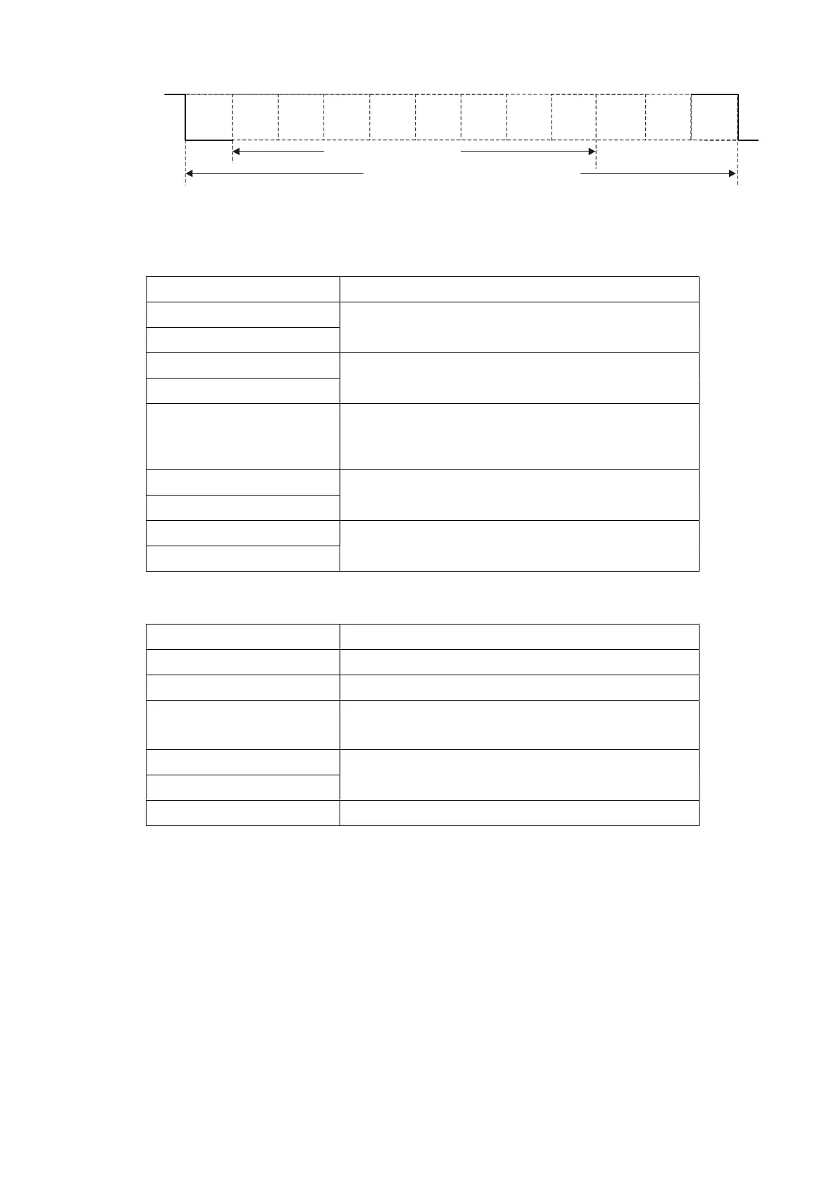
(8 , O , 2)
Start
bit
bit
12-bits character frame
Stop
bit
parity
Communication Protocol
1. Communication Data Frame
ASCII mode:
STX Start character ‘:’ (3AH)
Address Hi Communication address:
8-bit address consists of two ASCII codes.
Address Lo
Function Hi Command code:
8-bit command consists of two ASCII codes.
Function Lo
DATA (n-1) to DATA 0
Contents of data:
Nx8-bit data consists of 2n ASCII codes.
n ≤ 20, maximum of 40 ASCII codes.
LRC CHK Hi LRC checksum:
8-bit checksum consists of two ASCII codes.
LRC CHK Lo
END Hi End characters:
END1 = CR (0DH), END0 = LF (0AH)
END Lo
RTU mode:
START A silent interval of more than 10 ms
Address Communication address: 8-bit address
Function Command code: 8-bit command
DATA (n-1)
to
DATA 0
Contents of data:
n×8-bit data, n ≤ 40 (20 x 16-bit data).
CRC CHK Low
CRC checksum:
16-bit checksum consists of two 8-bit characters.
CRC CHK High
END A silent interval of more than 10 ms
2. Address (Communication Address)
Valid communication addresses are between 0–254. A communication address of 0 means broadcast to all
AC motor drives (AMD). In this case, the AMD broadcast does not reply with any message to the master
device.
00H: broadcast to all AC motor drives
01H: AC motor drive with address 01
0FH: AC motor drive with address 15
10H: AC motor drive with address 16
:
FEH: AC motor drive with address 254
For example, send communication to AMD with address 16 decimal (10H):
ASCII mode: Address = ’1’,’0’ => ‘1’ = 31H, ‘0’ = 30H
RTU mode: Address = 10H