EasyManua.ls Logo

Delta VFD040EL43W User Manual

Delta VFD040EL43W
197 pages
To Next Page IconTo Next Page
To Previous Page IconTo Previous Page
Page #119 background imageLoading...
Page #119 background image
Chapter 4 Parameters
VFD-EL-W
4-77
11: Modbus ASCII mode, protocol <7, O, 2>
Control by PC
1. When using RS-485 to connect with the communication port, you must set the communication address
for each VFD-EL-W drive in Pr.09.00 first so that the PC controls according to each address.
2. You can set a VFD-EL-W drive to communicate over Modbus networks using one of the following
modes: ASCII (American Standard Code for Information Interchange) or RTU (Remote Terminal Unit).
Select the desired mode along with the serial port communication protocol in this parameter.
3. Code Description:
The CPU delays about 1 second when using the communication reset; therefore, there is at least 1
second delay time in the master station.
ASCII mode:
Each 8-bit data is the combination of two ASCII characters. For example, a 1-byte data: 64 Hex, shown as
‘64’ in ASCII, consists of ‘6’ (36Hex) and ‘4’ (34Hex).
Character ‘0’ 1’ ‘2’ ‘3’ ‘4’ ‘5’ ‘6’ ‘7’
ASCII code 30H 31H 32H 33H 34H 35H 36H 37H
Character ‘8’ 9’ ‘A’ ‘B’ ‘C’ ‘D’ ‘E’ ‘F’
ASCII code 38H 39H 41H 42H 43H 44H 45H 46H
RTU mode:
Each 8-bit data is the combination of two 4-bit hexadecimal characters. For example, 64 Hex.
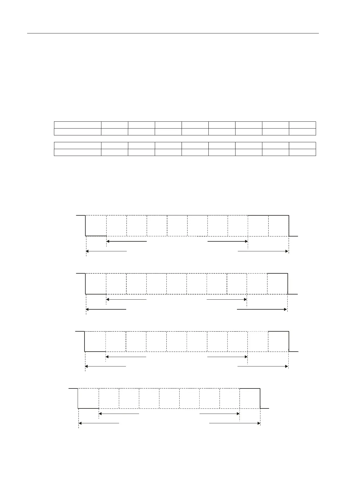
Data Format
Character Frame for ASCII:
7 , N , 2
Start
bit
0
1
2
3
4
5
6
Stop
bit
7-data bits
10-bits character frame
Stop
bit
7 , E , 1
Even
parity
Start
bit
0
1
2
3
4
5
6
Stop
bit
7-data bits
10-bits character frame
7 , O , 1
Odd
parity
Start
bit
0
1
2
3
4
5
6
Stop
bit
7-data bits
10-bits character frame
7 , N , 1
Start
bit
0
1
2
3
4
5
6
Stop
bit
7-data bits
9-bits character frame

Table of Contents

Question and Answer IconNeed help?

Do you have a question about the Delta VFD040EL43W and is the answer not in the manual?

Delta VFD040EL43W Specifications

General IconGeneral
BrandDelta
ModelVFD040EL43W
CategoryDC Drives
LanguageEnglish

Summary

Preface and Safety Precautions

Safety First: Installation Precautions

Essential safety guidelines for AC motor drive installation, emphasizing risks and protective measures.

Chapter 1: Introduction

Receiving and Inspection

Procedures for checking the AC motor drive upon arrival, including inspection for damage and part number verification.

Installation and Wiring Preparation

Guidelines for preparing the AC motor drive for installation and wiring, including environmental and storage conditions.

Drive Frames and Dimensions

Visual overview of different drive frames (A1, A2, B) and their physical dimensions for mounting and clearance.

RFI Jumper Location and Function

Explains the function and location of the RFI jumper, and procedures for its removal or installation.

Chapter 2: Installation and Wiring

Wiring Diagrams and Precautions

Detailed wiring instructions for main and control circuits, emphasizing safety and correct connections.

Main Circuit Terminals

Specifies terminal functions, wire gauge, and tightening torque for main circuit connections.

Control Terminals and Specifications

Details control terminal functions, wiring options (NPN/PNP), and specifications for analog/digital inputs.

Chapter 3: Keypad and Start-up

Digital Keypad Operation and Display

Explains the functions of the digital keypad, display messages, and operation flow for setting parameters.

Motor Trial Run Procedures

Steps for performing a trial run, checking motor rotation, and verifying smooth operation before formal use.

Chapter 4: Parameters

Parameter Summary and Applications

Overview of parameter groups and their application in specific functions like speed search, energy saving, and operation command.

User Parameters (Group 0)

Details for user-defined parameters including identity codes, parameter reset, and display settings.

Basic Parameters (Group 1)

Configuration settings for fundamental motor drive operations like output frequency, acceleration, and deceleration times.

Operation Method Parameters (Group 2)

Settings that define how the drive operates, including frequency command source and operation command source selection.

Output Function Parameters (Group 3)

Configuration of multi-function output relays and fan control for signaling and operational status.

Input Function Parameters (Group 4)

Settings for multi-function input terminals, potentiometer bias, and response time configurations.

Multi-Step Speed Parameters (Group 5)

Configuration for setting multiple discrete speed steps for the motor drive.

Protection Parameters (Group 6)

Settings for various protection functions like over-voltage, over-current, and thermal overload protection.

Motor Parameters (Group 7)

Configuration related to motor characteristics, including rated current, torque compensation, and auto-tuning.

Special Parameters (Group 8)

Advanced settings for DC brake, skip frequencies, auto-energy saving, and fire mode operations.

Communication Parameters (Group 9)

Settings for RS-485 communication, including address, transmission speed, and protocol configuration.

PID Control Parameters (Group 10)

Configuration settings for the Proportional-Integral-Derivative (PID) control loop for precise regulation.

Multi-pump SOP and Accessories

Standard operating procedures and accessory configurations for multi-pump systems, including wiring and parameter settings.

Chapter 5: Troubleshooting

Over-Current (oc) Troubleshooting

Diagnosing and resolving over-current faults by checking wiring, load, and acceleration/deceleration settings.

Over-Voltage (ov) Troubleshooting

Addressing over-voltage faults by verifying input voltage, regeneration, and deceleration time settings.

Low Voltage (Lv) Troubleshooting

Identifying causes of low voltage faults, including input power issues, heavy loads, and component malfunctions.

Overheat (oH1) Troubleshooting

Resolving overheat conditions by checking heat sink temperature, cooling fan, and ambient conditions.

Overload (oL) Troubleshooting

Diagnosing overload issues by checking load, settings, and potentially modifying drive capacity.

Keypad and Phase Loss Issues

Troubleshooting abnormal keypad displays and phase loss faults by checking connections and power input.

Motor Operation Faults

Diagnosing issues where the motor does not run, run as expected, or stalls during acceleration.

Noise and Environment Issues

Addressing electromagnetic noise and environmental conditions affecting drive performance and reliability.

Affecting Other Machines

Solutions for AC motor drives affecting other equipment, including harmonics and motor temperature rise.

Chapter 6: Fault Code Information and Maintenance

Fault Code Identification and Correction

Lists common fault codes, their descriptions, and corrective actions for troubleshooting AC motor drive errors.

Maintenance and Inspection Schedule

Outlines regular checks for ambient conditions, voltage, display, mechanical parts, and circuit components for preventive maintenance.

Resetting the Drive

Procedure for resetting the AC motor drive after a fault is cleared, ensuring safe operation.

Appendix A: Specifications

230V and 460V Series Specifications

Detailed electrical and physical specifications for the 230V single-phase and 460V three-phase VFD-EL-W series.

General Specifications and Environment

Overview of control, operating characteristics, functions, protection, and environmental requirements for the AC motor drive.

Derating Curves for Ambient Temperature and Carrier Frequency

Information on how ambient temperature and carrier frequency affect the drive's rated current, with derating curves.

Appendix B: Accessories

Circuit Breakers and Fuses

Recommended non-fuse circuit breakers and fuse specifications for one-phase and three-phase drives.

AC and Zero Phase Reactors

Recommended AC and zero phase reactor values for input circuits, including wiring diagrams and notes.

Digital Keypads (VFD-PU06, PU08)

Description, display explanations, and operation flow charts for VFD-PU06 keypad, and specifications for VFD-PU08/PU08V.

Optional Cooling Fan Kit

Details on installing an optional cooling fan to increase the ambient operating temperature limit for specific models.

Appendix C: Selecting the Right AC Motor Drive

Capacity Formulas and Calculations

Formulas and calculations for determining the required AC motor drive capacity based on motor and load characteristics.

General Precautions for Selection

Important considerations and precautions when selecting an AC motor drive, including power supply, motor type, and setting parameters.

Choosing a Suitable Motor

Guidance on selecting standard and special motors, considering torque, speed, and environmental factors for optimal performance with AC drives.

Related product manuals