Chapter 6 Control TerminalsME300
6-1
Chapter 6 Control Terminals
Analog input terminals (AI, ACM)
Analog input signals are easily affected by external noise. Use shielded wiring and
keep it as short as possible (less than 20 m) with proper grounding. If the noise is
inductive, connecting the shield to the ACM terminal can reduce interference.
Use twisted-pair wire for weak analog signals.
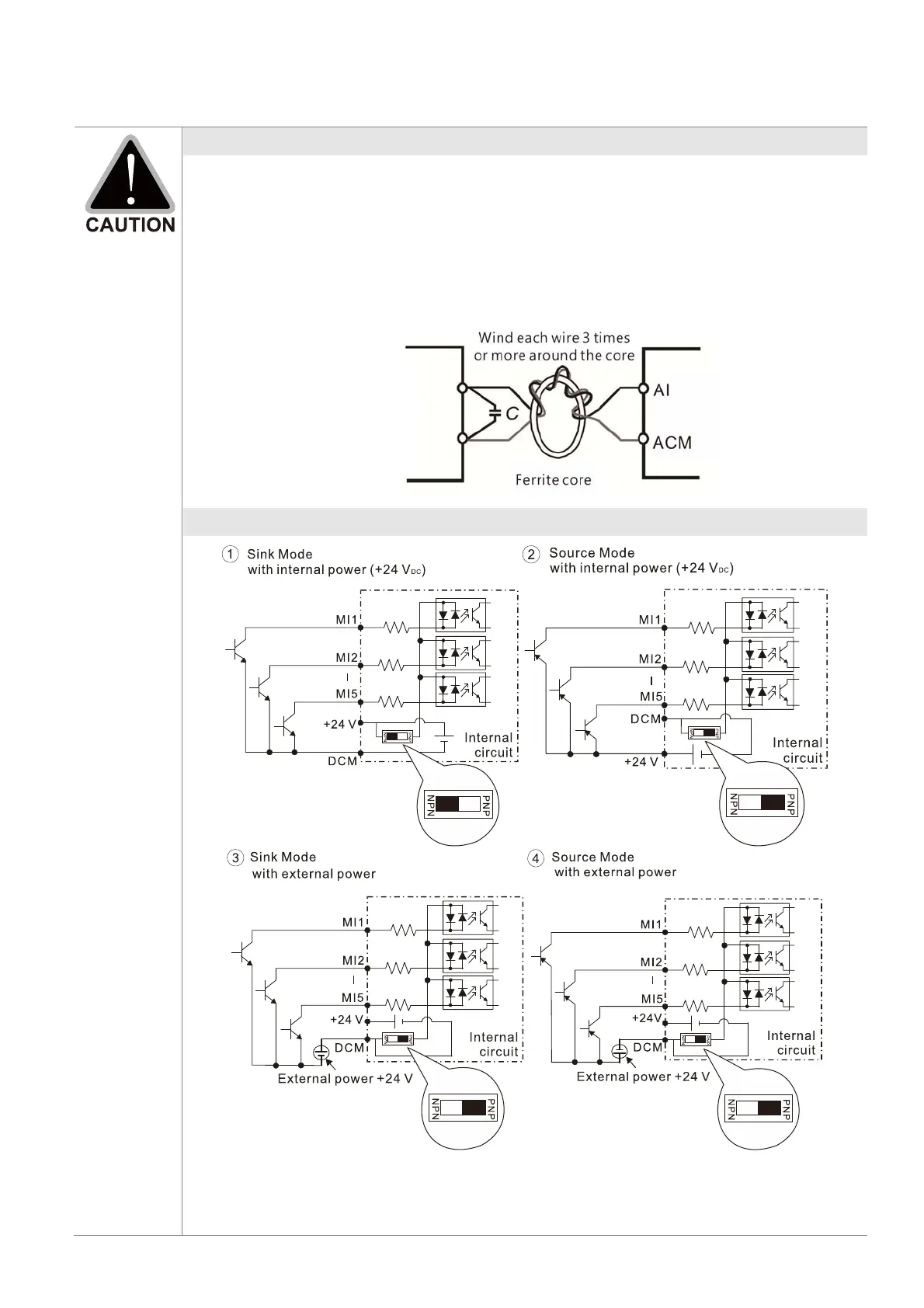
If the analog input signals are affected by noise from the drive, connect a capacitor
and ferrite core as shown in the following diagram.
Contact input terminals (MI1–MI5, DCM, +24 V)
When the photo coupler is using the internal power supply, the switch connection for
Sink and Source modes are as shown in the picture above: MI-DCM: Sink mode, MI-
+24 V: Source mode.
 Loading...