Chapter 12 Description of Parameter SettingsME300
12.1-07-13
Motor Shock Compensation Factor
Default: 1000
Settings 0–10000
If there are current wave motions in the motor in some specific area, setting this parameter can
effectively improve this situation. When running with high frequency or PG, set this parameter to
0. When the current wave motion occurs in low frequency and high-power, increase the value for
Pr.07-32.
Auto-restart Interval of Fault
Default: 60.0
Settings 0.0–6000.0 sec.
When a reset/restart occurs after a fault, the drive uses Pr.07-33 as a timer and starts counting
the number of faults within this time period. Within this period, if the number of faults does not
exceed the setting for Pr.07-11, the counting clears and starts from 0 when the next fault occurs.
Average PWM Signal
Default: 1
Settings 1–100 times
This parameter calculates the corresponding frequency command based on the average values
according to the set number of times for PWM signal period. The smaller the number of times set,
the faster the frequency changes.
PWM Signal Period
Default: 1
Settings 1–2000 ms
Sets the period for PWM signal input.
ME300 can control the operation frequency of the drive through PWM/pulse signal outputted from
devices such as PLC; however, PWM signal can only be input from MI5. You must set the Master
frequency command (AUTO) source Pr.00-20 to 4 (Pulse input without direction command) and
set pulse input type Pr.10-16 to 6 (PWM signal input). Pr.07-43 sets how long the PWM outputs a
command after how many times of averaging and sets the period of external PWM. The
corresponding output frequency calculates according to the settings for these two parameters.
When the actual input PWM pulse signal period is different from Pr.07-44 setting, the output
frequency calculates incorrectly.
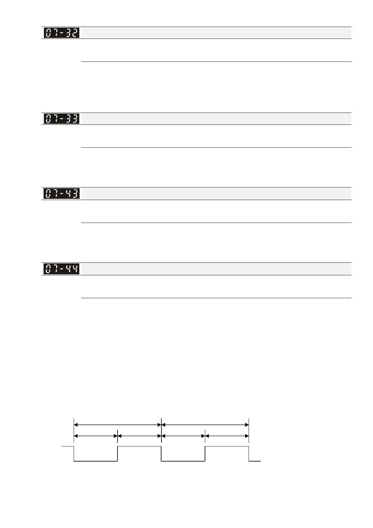
The relationship between PWM signal and frequency command shows as the diagram below:
Frequency command value (Hz) = (ON time / PWM period) x the maximum output frequency (Hz)
PWM Period
PWM Period
ON
Tr
OFF
Tr
ON (Tr) OFF (Tr)
PWM Voltage
Waveform
 Loading...