Chapter 6 Control TerminalsME300
6-3
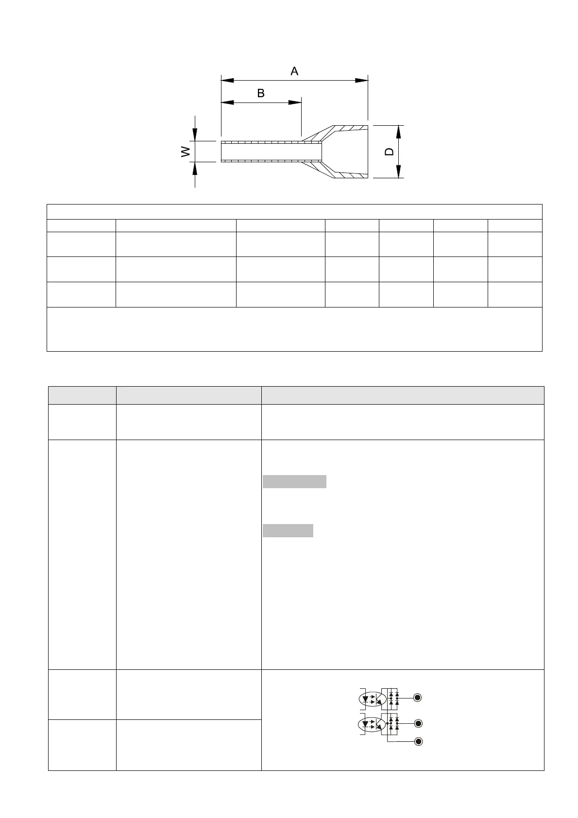
Unit: mm
Recommended model and size of crimp terminals
AWG VENDOR VENDOR P/N A (MAX) B (MAX) D (MAX) W (MAX)
0.25 mm
2
[24 AWG]
PHOENIX CONTACT AI 0,25- 8 YE 12.5 8 2.6 1.1
0.34 mm
2
[22 AWG]
PHOENIX CONTACT AI 0,34- 8 TQ 12.5 8 3.3 1.3
0.5 mm
2
[20 AWG]
PHOENIX CONTACT AI 0,5 - 8 WH 14 8 3.5 1.4
Recommended model and specifications of crimp tool:
CRIMPFOX 10S - 1212045, Manufacturer: PHOENIX CONTACT
DNT13-0101, Manufacturer: DINKLE
Terminals Terminal Function Description
+24 V
Digital control signal common
(Source)
+24 V±10% 100 mA
MI1
–
MI5
Multi-function input 1–5
Refer to Pr.02-01–Pr.02-05 to program the multi-function
inputs MI1–MI5.
Source Mode
ON: the activation current is 3.3 mA ≥
11 V
DC
OFF: cut-off voltage ≤ 5 V
DC
Sink Mode
ON: the activation current is 3.3 mA ≤
13 V
DC
OFF: cut-off voltage ≥
19 V
DC
When Pr.02-00 = 0, MI1 and MI2 can be programmed.
When Pr.02-00 ≠ 0, the function of MI1 and MI2 is
according to Pr.02-00 setting.
When MI5 uses pulse input, the maximum input
frequency = 10 kHz.
When MI5 uses PWM pulse input, the maximum input
frequency = 1 kHz.
MO1
Multi-function Output 1
(photo coupler)
Programmable open-collector outputs, see Pr.02-16.
MO2
MCM
MO1
Max 48 V
DC
50 mA
MCM
Multi-function Output
Common
 Loading...