Chapter 12 Descriptions of Parameter SettingsMS300
423
10 Speed Feedback Control Parameters
In this parameter group, ASR is the abbreviation for Adjust Speed Regulator.
You can set this parameter during operation.
MI7 Single-Phase Pulse Input Type Selection
When you use MI7 single-phase pulse input, you must use it with Pr.00-20 = 4, Pr.10-00 = 5 and
Pr.10-16 = 5.
When you use MI7 single-phase pulse input as speed feedback, you must use it with Pr.10-00 =
5 and Pr.10-02 = 5. The drive calculates the MI7 single-phase pulse input speed when the
control modes are VF, VFPG, SVC IM/PM FOC sensorless, and IM/PM TQC
The MS300 does not support the full position control pulse command input function.
MI7 Single-Phase Pulse Input Pulses per Revolution
This parameter sets the MI7 single-phase pulse input pulses per revolution (ppr). It is a feedback
control signal source when using pulses. The MI7 single-phase pulse input sets the number of
pulses for the motor rotating through one rotation. The A/B phase cycle generates the pulse
number.
This setting is also the MI7 single-phase pulse input resolution. The speed control is more
accurate with higher resolution.
If you set this parameter incorrectly, it may cause motor stall, drive over-current, or a permanent
magnetic pole origin detection error for the PM motor in closed-loop control. When using the PM
motor, you must perform the magnetic pole origin detection (Pr.05-00 = 13) again if you modify
the content of this parameter.
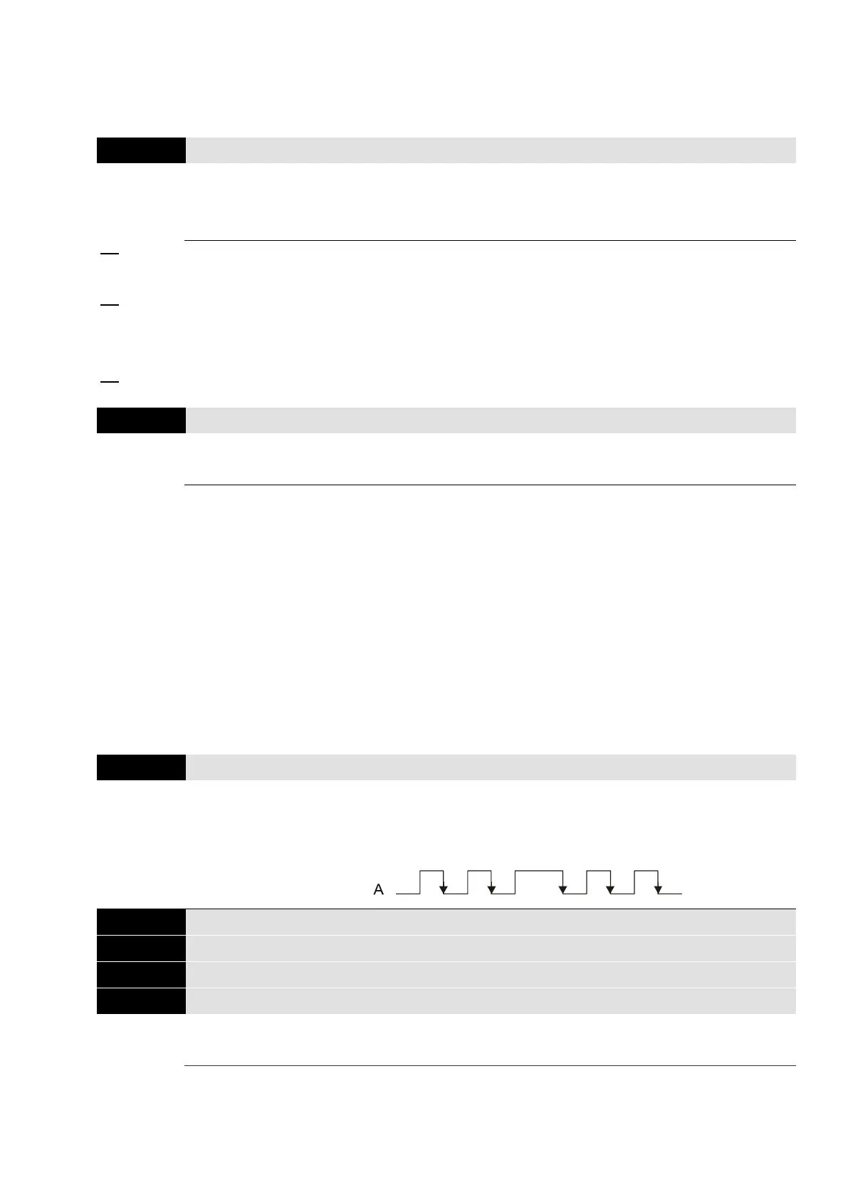
Encoder Input Type Setting
5: Single-phase input (MI7)
Mechanical Gear at Load Side A1
Mechanical Gear at Motor Side B1
Mechanical Gear at Load Side A2
Mechanical Gear at Motor Side B2
Use Pr.10-04–Pr.10-07 with the multi-function input terminal setting 48 to switch to Pr.10-04–
Pr.10-05 or Pr.10-06–Pr.10-07, as shown in the diagram below.
 Loading...

