EasyManua.ls Logo

Delta VFD2A8MS21ANSAA User Manual

Delta VFD2A8MS21ANSAA
805 pages
To Next Page IconTo Next Page
To Previous Page IconTo Previous Page
Page #774 background imageLoading...
Page #774 background image
Chapter 16 PLC Function ApplicationsMS300
765
16-9 Count Function Using Pulse Input
16-9-1 High-speed count function
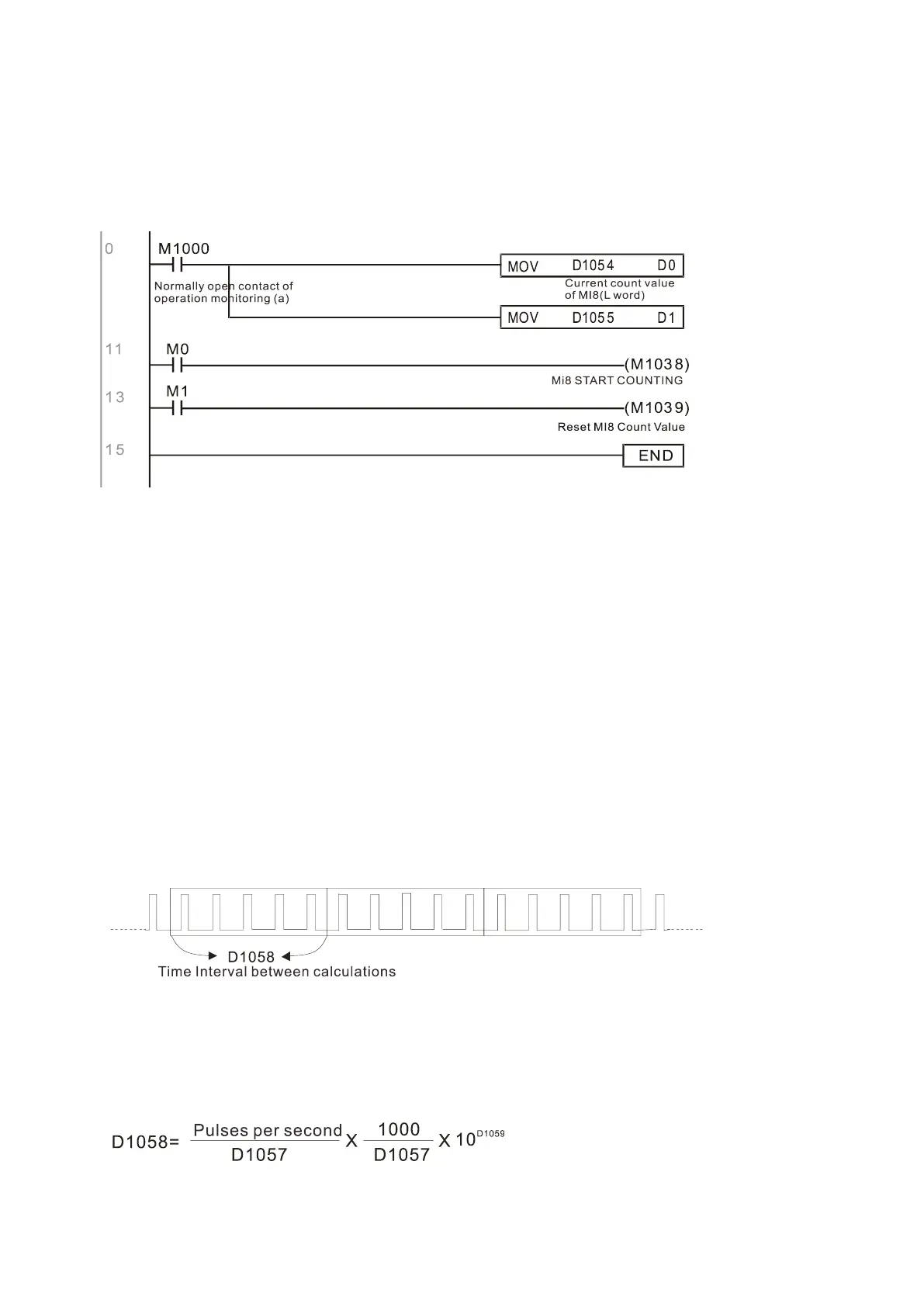
The MS300's MI7 supports one-way pulse counting with a maximum speed of 33 k. The starting
method is very simple, and only requires setting M1038 to begin counting. The 32-bit count value is
stored in D1054 and D1055 in non-numerical form. M1039 resets the count value to 0.
NOTE: When the PLC program defines MI7 for use as a high-speed counter, that is, when M1038 or
M1039 is written in PLC procedures, other functions of MI7 are disabled.
16-9-2 Frequency calculation function
Apart from high-speed counting, the MS300's MI7 can also convert a received pulse to a frequency.
The following figure shows that there is no conflict between frequency conversion and count
calculations, which the MS300 can perform simultaneously.
PLC speed calculation formula
D1057 Speed
D1058 Interval between calculations
D1059 Decimal places
Assume that there are five input pulses each second, (see figure below) we set D1058 = 1000 ms =
1.0 second as the calculation interval. This enables five pulses to be sent to the drive each second.
Assume that each five pulses correspond to 1 Hz, we set D1057 = 5.
Setting D1059 = 2 displays numbers to two decimal places, which is also 1.00 Hz. The numerical
value displayed at D1056 is 100. For simplicity, the D1059 conversion formula can be expressed in
the following formula:
Current count value
of MI8(H word)

Table of Contents

Other manuals for Delta VFD2A8MS21ANSAA

Questions and Answers:

Delta VFD2A8MS21ANSAA Specifications

General IconGeneral
Protection LevelIP20
Control MethodV/F Control, Sensorless Vector Control
Frequency Range0.1-400Hz
Protection FeaturesOver-voltage, Over-current, Overload, Overheat, Low-voltage, Ground Fault, Short Circuit
Cooling MethodFan Cooling
Operating Temperature-10°C to 50°C
Storage Temperature-20°C to 60°C
Altitude1000m

Summary

Introduction

Important points regarding ground connection

Key safety regulations and correct/incorrect methods for grounding the motor drive and equipment.

Installation

3-1 Mounting Clearance

Specifies minimum required clearances (A, B, C) for single drive, side-by-side, and zero stack installations based on ambient temperature.

3-2 Airflow and Power Dissipation

Provides airflow rates and power dissipation values for various AC motor drives across different frames (A, B, C, D, E, F).

Wiring

4-1 System Wiring Diagram

Illustrates the system wiring diagram for power input, NFB/fuse, electromagnetic contactor, AC/DC reactors, and EMC filter.

4-2 Wiring

Details on input wiring for single-phase/three-phase power and wiring precautions for power and control terminals.

Main Circuit Terminals

5-1 Main Circuit Diagram

Provides a diagram of the main circuit terminals including R/L1, S/L2, T/L3, U/T1, V/T2, W/T3, DC-/DC+/+1, +2/B1, B2, and ground connection.

Control Terminals

6-1 Control Terminal Specifications

Details wiring specifications for Relay and Control terminals, including stripping length, wire gauge, and tightening torque.

Optional Accessories

7-1 Brake Resistors and Brake Units Used in AC Motor Drives

Lists brake resistors and brake units suitable for AC motor drives, including part numbers, specifications, and torque values.

7-14 Digital Keypad - KPC-CC01

Describes the KPC-CC01 digital keypad, its communication interface, protocol, installation method, and function descriptions.

Specifications

Digital Keypad

10-2 Keypad Operation Process

Details the operational processes for the keypad, including main page selection, setting parameters, shifting data, and PLC settings.

Summary of Parameter Settings

06 Protection Parameters (1)

Details protection parameters including low voltage level, over-voltage stall prevention, over-current stall prevention, and over-torque detection.

09 Communication Parameters

Summarizes communication parameters such as address, transmission speed, fault treatment, time-out detection, protocol, and block transfers.

14 Protection Parameters (2)

Lists protection parameters for output frequency, DC bus voltage, output current, and IGBT temperature malfunctions.

Descriptions of Parameter Settings

Warning Codes

Summary of Warning Codes

Lists all warning codes with their ID, display on LCD, name, description, and recommended error resolution.

Fault Codes

Summary of Fault Codes

Provides a comprehensive list of fault codes, including ID, display on LCD, fault name, fault descriptions, and corrective actions.

CANopen Overview

15-2 Wiring for CANopen

Provides instructions for CANopen wiring using an external communication card CMM-COP01 and RJ45 cable with terminating resistors.

PLC Function Applications

Safe Torque Off Function

17-3 Wiring Diagram

Provides wiring diagrams for the safe control loop, including internal circuit and STO wiring.

17-7 Error Code and Troubleshooting Instructions

Explains error codes related to STO/STL functions and provides troubleshooting instructions based on keypad display.

Appendix A. Modbus Protocol

Related product manuals