Explanatory Photos for DISASSEMBLY
• For the shooting direction of each photos used in this manual, see the photo below.
• A, B, C and D in the photo below indicate the shooting directions of photos.
• The photographs with no shooting direction indicated were taken from the top of the unit.
• Photos of AVR-X2400H E3 are used in this manual.
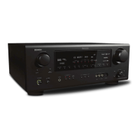
The viewpoint of each photograph
(Shooting direction : X) [View from the top]
Proceeding : TOP COVER → WiFi ANT
(1) Remove the INSULATION SHEET. Cut the wire clamps.
NOTE :
・If the INSULATION SHEET has been removed, replace with a new sheet.
・ When attaching the INSULATION SHEET, align with the Silk-Print and up to side of the NETWORK
MODULE PCB.
・Turn up and spare wire at position A.
↓Shooting direction: C↓
↑Shooting direction: D↑
↑Shooting direction: A↑
↓Shooting direction: B↓
1. WiFi ANT
↑Shooting direction: A↑
INSULATION SHEET
�
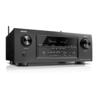
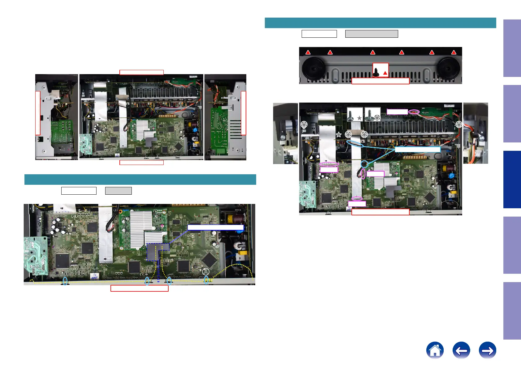
Proceeding : TOP COVER → FRONT PANEL ASSY
(1) Remove the screws.
(2) Remove the screws. Remove the CORD HOLDER and connectors. Remove the FFC.
2. FRONT PANEL ASSY
View from the bottom
x6
↑Shooting direction: A↑
x4x1
FFC
FFC
N1008
CP4400
CORD HOLDER
67
Caution in
servicing
Electrical Mechanical Repair Information Updating
 Loading...