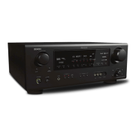
Proceeding : TOP COVER → RADIATOR ASSY
(1) Remove the screws.
(2) Remove the screws. Remove the CORD HOLDER and connectors. Remove the FFC.
(3) Remove the connector.
3. RADIATOR ASSY
View from the bottom
↓Shooting direction: D↓ ↓Shooting direction: C↓
x7
↑Shooting direction: A↑
x2x1
FFC
FFC
N1008
CP4400
CORD HOLDER
CP401
CP402 CP405CP403
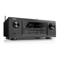
Proceeding : TOP COVER → WiFi ANT → DIGITAL PCB
(1) Remove the screws.
(2) Cut the wire clamps, then remove the CORD HOLDERs and connectors.
Remove the FFC.
(3) Remove the connector.
4. DIGITAL PCB
↑Shooting direction: A↑
x28
x13
x2
x2 E3 ONLY
↑Shooting direction: A↑
x1
x1
N1008
FFC
FFC
N1033
N1019
CUT
CUT
CUT
CUT
N1039
N1014
N1016
N1020
68
Caution in
servicing
Electrical Mechanical Repair Information Updating
 Loading...