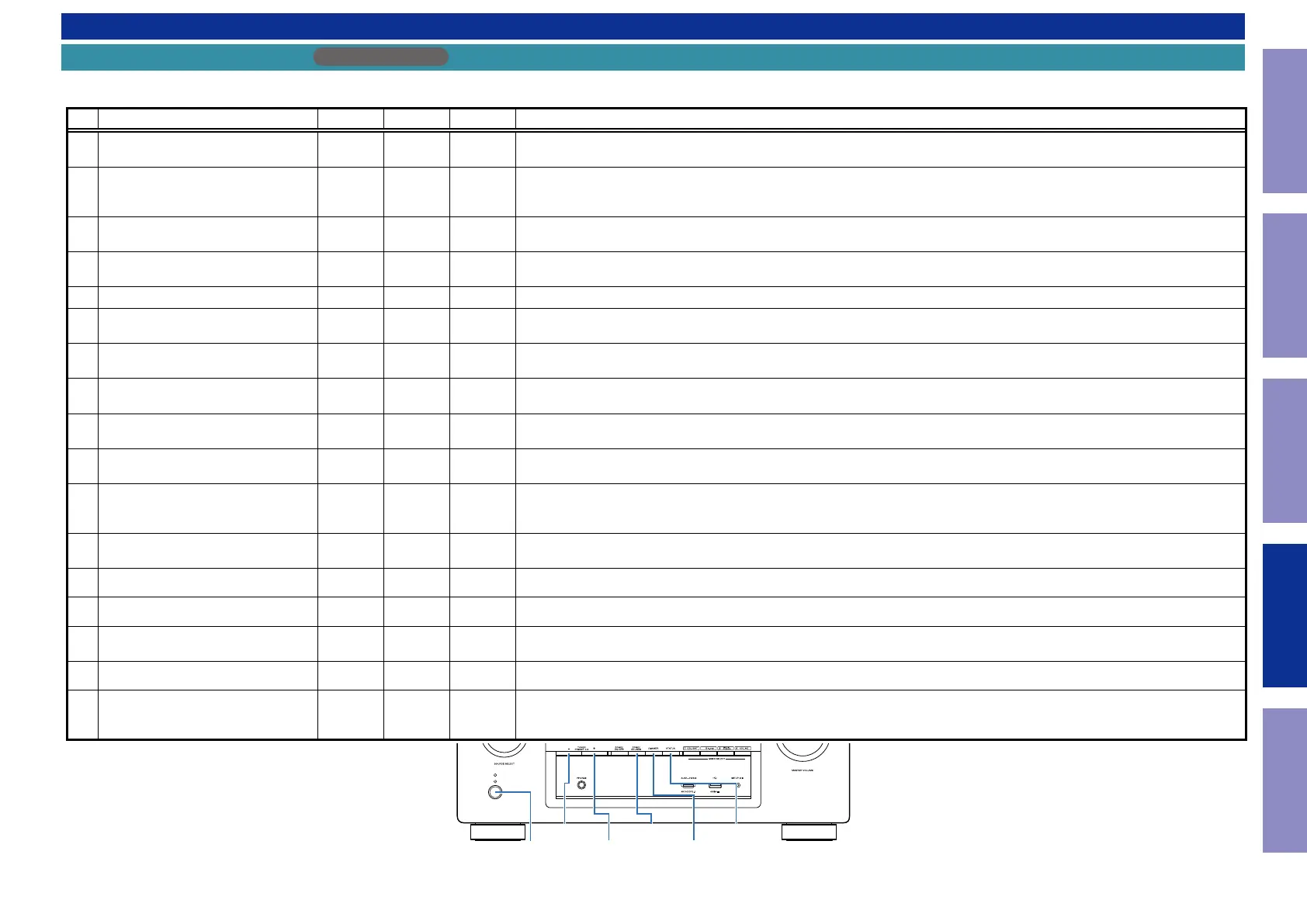
SPECIAL MODE
Special mode setting button
AVR-X2300W
b
No. 1 - 8 : While holding down buttons "
A
", "
B
" and "
C
" simultaneously, press the power button to turn on the power.
b
No. 9 : While holding down buttons "
A
", "
B
" and "
C
" simultaneously, insert the AC plug into the wall outlet to turn on the power.
No. Mode Button A Button B Button C Descriptions
1
Version Display
(u-COM / DSP Error Display)
DIMMER STATUS -
Displays the version of rmware such as the main rmware or DSP. Errors that have occurred are displayed.
(See 1. Version Display Mode)
2
PANEL / REMOTE LOCK Selection
Mode
TUNER
PRESET CH +
ZONE2
SOURCE
-
Start this unit in the PANEL/REMOTE LOCK selection mode so that PANEL LOCK and Remote Lock can be switched between On
and Off. (See 2. PANEL / REMOTE LOCK Selection Mode)
PANEL LOCK MODE : No. 2 - 1 - No. 2 - 3
2-1
PANEL LOCK Mode
(with Volume)
↑ ↑ -
Disables reception from all keys and encoders on the front panel except the power button (including the volume).
2-2
PANEL LOCK Mode
(without Volume)
↑ ↑ -
Disables reception from all keys and encoders on the front panel except the power button and volume encoder.
2-3 PANEL LOCK mode is turned off
↑ ↑ -
Releases the PANEL LOCK.
3 Selecting the Mode for Service-related
ZONE2
SOURCE
DIMMER STATUS
This is a display for turning on each service-related mode.
Service-related modes: No. 3-1 - No. 3-5
3-1 Check the Video/Audio path Mode
↑ ↑ ↑
This is a special mode for service conrmation used during repair work to simplify the conrmation work for the Audio channel /
video channel. (See DIAGNOSTIC MODE)
3-2 Protection history display mode
↑ ↑ ↑
Displays the protection occurrence history.
(See 3-2. Protection History Display Mode)
3-3 Operation Info Mode
↑ ↑ ↑
Displays the accumulated operating time of the unit, the number of times the power was switched on, and the number of occur-
rences of each protection. (See 3-4. Operation Info Mode)
3-4
TUNER STEP Mode
(E3 and E2 model only)
↑ ↑ ↑
Enables reception STEP of the ANALOG TUNER to be changed.
(See 3-5. TUNER STEP mode (E2 / E3 only))
3-5 Remote ID Setup Mode
↑ ↑ ↑
If there are multiple DENON AV receivers in the same area, this mode prevents other AV receivers from being operated concur-
rently with this device.
(See 3-6. Remote ID Setup Mode)
4 Protection Pass Mode
TUNER
PRESET CH +
ZONE2
SOURCE
STATUS
Enables the power to be turned on when protection detection is disabled.
(See 4. Protection Pass Mode)
5 User Initialization Mode
TUNER
PRESET CH -
TUNER
PRESET CH +
-
Initializes backup data. (Settings for the Installer Setup are not initialized.) (Reboot the CY920)
6 Factory Initialization Mode
ZONE2
SOURCE
DIMMER -
Initializes backup data. (Settings for the Installer Setup are initialized.) (CY920 is not Reboot) (See CAUTION IN SERVICING.)
7 Clearing the Operation Info
ZONE2
SOURCE
STATUS -
Clear the accumulated operating time of the unit, the number of times the power was switched on, and the number of occur-
rences of each protection. (See 7. Clearing the Operation Info)
8 USB Update Mode
TUNER
PRESET CH +
STATUS -
Switches this unit to USB Update mode. (See 2. Updating via USB)
9 Forced USB All Device Write Mode
TUNER
PRESET CH +
STATUS -
Mode used when this unit cannot be recovered.
Forcibly switches this unit to USB update mode.
(See 2.9. Forced USB All Device Write Mode)
DIMMER
STATUSTUNER
PRESET CH -
TUNER
PRESET CH +
X
ZONE2
SOURCE
108
Caution in
servicing
Electrical Mechanical Repair Information Updating
 Loading...