ENGLISH
10
Fig. T
10
51
Compound Mitering
This is a combination of bevel crosscutting and mitering. Follow the instructions for both bevel
crosscutting andmitering.
Non-Through-Cutting (Grooving and Rabbeting)
WARNING: Remove the blade guard assembly
11
and install the non-through-cutting
riving knife
21
for non-through-cutting operations. Use featherboards for all non-through-
cutting operations where the blade guard assembly, anti-kickback assembly and riving kife
cannot beused.
Instructions in the Ripping, Crosscutting, Bevel Crosscutting, Mitering, and Compound
Mitering sections are for cuts made through the full thickness of the material. The saw can also
perform non-through cuts to form grooves or rabbets in thematerial.
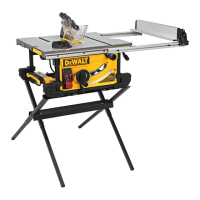
Non-Through-Ripping (Fig. U, E)
WARNING: A rip fence should ALWAYS be used for ripping operations to prevent loss of
control and personal injury. NEVER perform a ripping operation freehand. ALWAYS lock the
fence to therail.
WARNING: When bevel ripping and whenever possible, place the fence on the side of the
blade so that the blade is tilted away from the fence andhands.
WARNING: Keep hands clear of theblade. With non-through-cutting the blade is not
always visible during the cut, so increased caution is necessary to ensure hands are clear of
theblade.
WARNING: Use a push stick to feed the workpiece if there are 2–6" (51–152mm) between
the fence and the blade. Use a narrow ripping fence feature and push block to feed the
workpiece if there are 2" (51mm) or narrower between the fence and theblade.
1. Remove the blade guard assembly
11
and install the non-through-cutting riving knife
21
(Fig. E). Refer to Installing/Removing the Blade Guard Assembly and RivingKnife.
2. Lock the rip fence by pressing the rail lock lever down. Remove the mitergauge.
3. Raise the blade to the desired cutdepth.
4. Hold the workpiece flat on the table and against the fence. Keep the workpiece about 1"
(25.4mm) away from theblade.
Fig. U
WARNING: The workpiece must have a straight edge against the fence and must not be
warped, twisted or bowed. Keep both hands away from the blade and away from the path of
the blade. See proper hand position in FigureU.
5. Turn the saw on and allow the blade to come up to speed. Both hands can be used in starting
the cut. When there are approximately 12" (305mm) left to be ripped, use only one hand,
with your thumb pushing the material, your index and second finger holding the material
down and your other fingers hooked over the fence. Always keep your thumb along side your
first two fingers and near thefence.
6. Keeping the workpiece against the table and fence, slowly feed the workpiece rearward all
the way through the saw blade. Continue pushing the workpiece until it is clear of the blade
guard assembly and it falls off the rear of the table. Do not overload themotor.
7. Never try to pull the workpiece back with the blade turning. Turn the switch off, allow the
blade to stop and slide the workpieceout.
8. When sawing a long piece of material or a panel, always use a work support. A sawhorse,
rollers, or out feed assembly provides adequate support for this purpose. The work support
must be at the same height or slightly lower than the sawtable.
Non-Through-Ripping Small Pieces (Fig. A)
It is unsafe to rip small pieces. It is not safe to put your hands close to the blade. Instead, rip a
larger piece to obtain the desired piece. When a small width is to be ripped and the hand cannot
be safely put between the blade and the rip fence, use one or more push sticks. A pattern is
included at the end of this manual to make push sticks. A push stick
20
is included with this saw,
attached to the rip fence. Use the push stick(s) to hold the workpiece against the table and fence,
and push the workpiece fully past theblade.
Non-Through-Bevel Ripping (Fig. V)
This operation is the same as non-through-cut ripping except the bevel angle is set to an angle
other than zero degrees. For proper hand position, Refer to FigureV.
Fig. V
WARNING: Before connecting to power source or operating the saw, always inspect the
riving knife for proper alignment and clearance with saw blade. Check alignment after each
change of bevelangle.
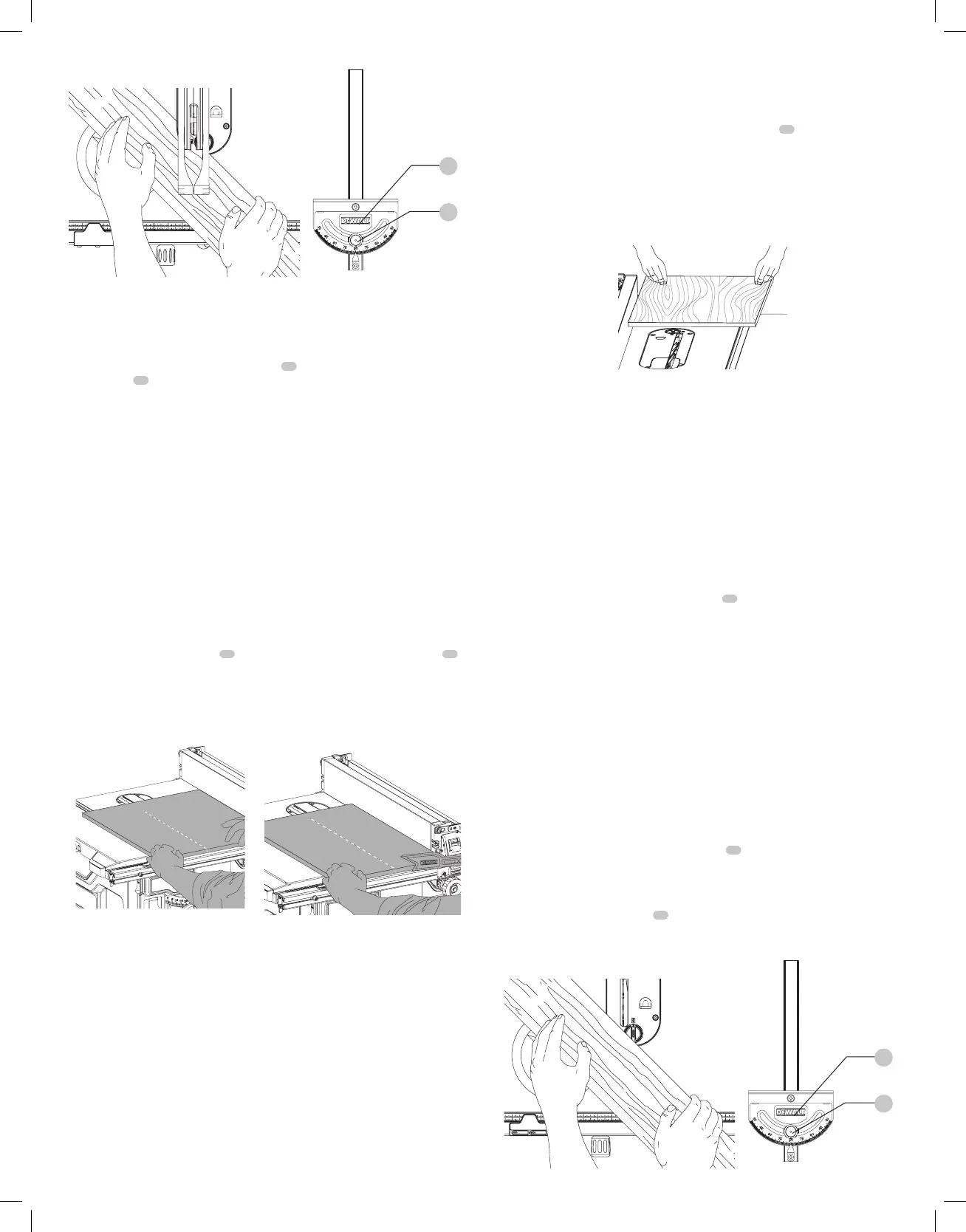
Non-Through-Crosscutting (Fig. W)
WARNING: NEVER use rip fence in combination with mitergauge.
WARNING: To reduce the risk of injury, NEVER use the fence as a guide or length stop
whencrosscutting.
WARNING: When using a block as a cut-off gauge, the block must be at least 3/4" (19mm)
thick and is very important that the rear end of the block be positioned so the workpiece
is clear of the block before it enters the blade to prevent contact with blade resulting in a
thrown workpiece and possiblyinjury.
1. Remove the rip fence and place the miter gauge in the desiredslot.
2. Adjust the blade height to the desired cutdepth.
3. Hold the workpiece firmly against the miter gauge
10
with the path of the blade in line with
the desired cut location. Keep the workpiece an inch or so in front of the blade. KEEP BOTH
HANDS AWAY FROM THE BLADE AND THE PATH OF THE BLADE (Fig. W).
4. Start the saw motor and allow the blade to come up tospeed.
5. While using both hands to keep the workpiece against the face of the miter gauge, and
holding the workpiece flat against the table, slowly push the workpiece through theblade.
6. Never try to pull the workpiece with the blade turning. Turn the switch off, allow the blade to
stop, and carefully slide the workpieceout.
Non-Through-Bevel Crosscutting
This operation is the same as crosscutting except that the bevel angle is set to an angle other
than 0°.
WARNING: Before connecting connecting to power source or operating the saw, always
inspect the riving knife for proper alignment and clearance with saw blade. Check alignment
after each change of bevelangle.
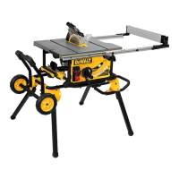
Non-Through-Mitering (Fig. W)
This operation is the same as crosscutting except the miter gauge is locked at an angle other than
0°. Hold the workpiece FIRMLY against the miter gauge
10
and feed the workpiece slowly into
the blade (to prevent the workpiece from moving).
Non-Through-Miter Gauge Operation
To set your miter gauge:
1. Loosen the miter gauge lockknob
51
.
2. Move the miter gauge to the desiredangle.
3. Tighten the miter gauge lockknob.
Fig. W
10
51

 Loading...