ENGLISH
4
Motor
Be sure your power supply agrees with the nameplate marking. Voltage decrease of more than
10% will cause loss of power and overheating. These tools are factory tested; if this tool does not
operate, check power supply.
The label on your tool may include the following symbols. The symbols and their definitions are
asfollows:
V
......................... volts
Hz .......................hertz
min
..................... minutes
or DC ......direct current
...................... Class I Construction (grounded)
…/min ..............per minute
BPM
.................... beats per minute
IPM
..................... impacts per minute
RPM
.................... revolutions per minute
sfpm ................... surface feet per minute
SPM .................... strokes per minute
OPM
.................... oscillations per minute
A ......................... amperes
W
........................watts
or AC ...........alternating current
or AC/DC .... alternating or direct current
...................... Class II Construction (double insulated)
n
o
.......................no load speed
n
.........................rated speed
......................earthing terminal
.....................safety alert symbol
.....................visible radiation
..................... avoid staring at light
..................... wear respiratory protection
..................... wear eye protection
..................... wear hearing protection
..................... read all documentation
IPXX .................... IP symbol
Additional Safety Information
WARNING: Never modify the power tool or any part of it. Damage or personal injury
couldresult.
WARNING: ALWAYS use safety glasses. Everyday eyeglasses are NOT safety glasses. Also use
face or dust mask if operation is dusty. ALL USERS AND BYSTANDERS MUST ALWAYS WEAR
CERTIFIED SAFETYEQUIPMENT:
• ANSI Z87.1 eye protection (CAN/CSA Z94.3),
• ANSI S12.6 (S3.19) hearing protection,
• NIOSH/OSHA/MSHA respiratoryprotection.
WARNING: Some dust created by power sanding, sawing, grinding, drilling, and other
construction activities contains chemicals known to the State of California to cause cancer,
birth defects or other reproductive harm. Some examples of these chemicalsare:
• lead from lead-based paints,
• crystalline silica from bricks and cement and other masonry products, and
• arsenic and chromium from chemically-treatedlumber.
Your risk from these exposures varies, depending on how often you do this type of work.
To reduce your exposure to these chemicals: work in a well ventilated area, and work with
approved safety equipment, such as those dust masks that are specially designed to filter out
microscopicparticles.
• Avoid prolonged contact with dust from power sanding, sawing, grinding, drilling, and
other construction activities. Wear protective clothing and wash exposed areas with
soap and water. Allowing dust to get into your mouth, eyes, or lay on the skin may promote
absorption of harmfulchemicals.
WARNING: Use of this tool can generate and/or disperse dust, which may cause serious
and permanent respiratory or other injury. Always use NIOSH/OSHA approved respiratory
protection appropriate for the dust exposure. Direct particles away from face andbody.
WARNING: Always wear proper personal hearing protection that conforms to ANSI
S12.6 (S3.19) during use. Under some conditions and duration of use, noise from this
product may contribute to hearingloss.
• Air vents often cover moving parts and should be avoided. Loose clothes, jewelry or long
hair can be caught in movingparts.
• An extension cord must have adequate wire size (AWG or American Wire Gauge) for
safety. The smaller the gauge number of the wire, the greater the capacity of the cable, that is,
16 gauge has more capacity than 18gauge. An undersized cord will cause a drop in line voltage
resulting in loss of power and overheating. When using more than one extension to make up
the total length, be sure each individual extension contains at least the minimum wire size. The
following table shows the correct size to use depending on cord length and nameplate ampere
rating. If in doubt, use the next heavier gauge. The lower the gauge number, the heavier thecord.
Minimum Gauge for Cord Sets
Volts
Total Length of Cord in Feet
(meters)
120V 25 (7.6) 50 (15.2) 100 (30.5) 150 (45.7)
240V 50 (15.2) 100 (30.5) 200 (61.0) 300 (91.4)
Ampere Rating
American Wire Gauge
More
Than
Not
More
Than
0 6 18 16 16 14
6 10 18 16 14 12
10 12 16 16 14 12
12 16 14 12 Not Recommended
Saw Blades
• Do not use saw blades that do not conform to the dimensions stated in the Specifications.
Do not use any spacers to make a blade fit onto the spindle. Use only the blades specified in this
manual, complying with EN847-1, if intended for wood and similarmaterials.
• Consider applying specially designed noise-reductionblades.
• Do not use high steel (HS) sawblades.
• Do not use cracked or damaged sawblades.
• Ensure that the chosen saw blade is suitable for the material to becut.
• Always wear gloves for handling saw blades and rough material. Saw blades should be carried in
a holder whereverpracticable.
Specifications
Table Size 19 X 19" (485 x 485mm)
Miter Angle 30° left and right
Bevel Angle -2° to 47° left
Blade Size 8–1/4" (210mm)
Max. Cut Depth, 0° Bevel 2–9/16" (65mm)
Max. Cut Depth, 45° Bevel 1–3/4" (45mm)
RPM, no load 5800
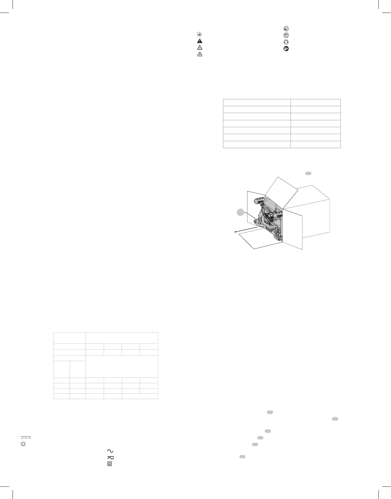
Unpacking (Fig.B)
WARNING: To reduce the risk of injury, DO NOT connect the machine to the power source
until the table saw is completely assembled and you have read the entire instruction manual.
Open the box and slide the saw out using the carrying handle
22
, as shown in Figure B.
Fig. B
22
Carefully unpack the table saw and all loose items from the carton. Examine all parts to make sure
that parts have not been damaged during shipping. If any parts are missing or damaged, contact
your dealer to replace them before attempting to assemble thetool.
COMPONENTS FIG. A
WARNING: Never modify the power tool or any part ofit. Damage or personal injury
couldresult.
Refer to Figure A at the beginning of this manual for a complete list ofcomponents.
Intended Use
This table saw is intended for use by construction professionals for use in ripping, crosscutting,
mitering, beveling and non-through cutting applications in wood, plastic, and other
softmaterials.
DO NOT use for cutting metal, cement board, ormasonry.
DO NOT use dado sets, multiple blades or shaping cutter heads on thissaw.
DO NOT perform tapered cuts without a tapered jigaccessory.
DO NOT use the saw for plunge or covecutting.
DO NOT use under wet conditions or in presence of flammable liquids orgases.
DO NOT let children come into contact with the tool. Supervision is required when inexperienced
operators use thistool.
ASSEMBLY
WARNING: Shock Hazard. To reduce the risk of serious personal injury, turn unit off
and disconnect machine from power source before attempting to move it, change
accessories or make any adjustments. An accidental start-up can cause injury.
Assembly Order (Fig. A)
1. Unlock and remove the throat plate
15
. Refer to: Removing the Throat Platesection.
2. Make sure blade is installed correctly and arbor nut is tight. Use wrenches
19
stored on the
tool. Refer to FigureA.
3. Position the blade guardassembly
11
.
4. Attach anti-kickback assembly
12
to the guardassembly.
5. Install and lock throat plate
15
. (NOTE: Adjust leveling screws before proceeding. Refer to
Installing the Throat Plate.)
6. Attach the rip fence
16
. (NOTE: Adjust rip scale before proceeding. Refer to Adjusting the
RipScale.)

 Loading...