10
INSTALLATION INSTRUCTIONS
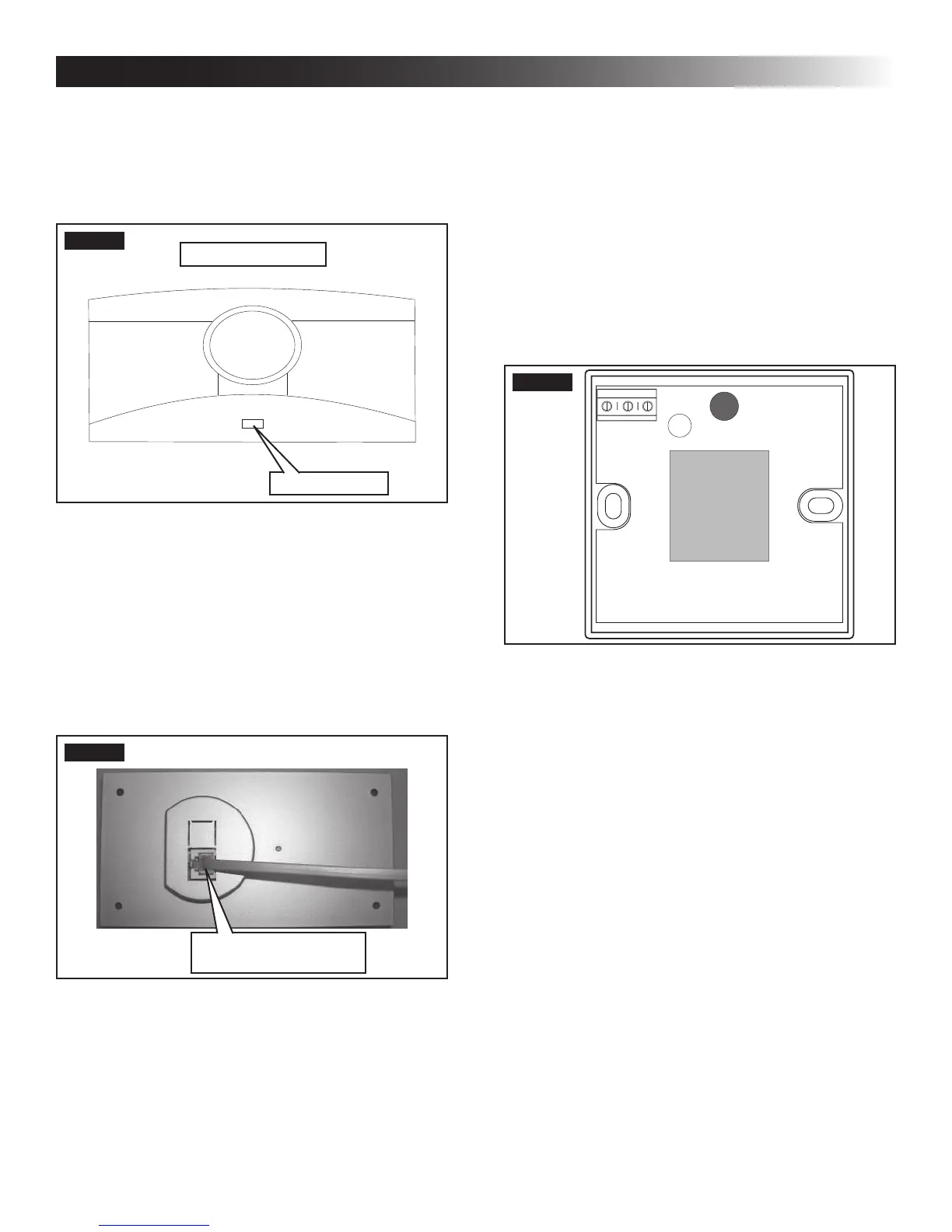
d. Thermostat Installation
I. Carefully separate the thermostat base
plate from the thermostat cover. Insert a
small screw driver into the slot on bottom
of thermostat and disengage the tab. See
(FIG. 11).
FIG. 11
Disengage Tab
CCC 2 Thermostat
II. Insert the 4 conductor communication ca-
ble through the hole in base plate. Align
thermostat base plate with hole in wall.
Make sure base plate is level and attach
base plate to wall using the four (4) sup-
plied screws.
III. Insert the 4 conductor communication
cable connector (RJ-11-6C4P) into the
connector on the back of the thermostat.
See (FIG. 12).
FIG. 12
4 Conductor
Communication Cable
IV. Align the thermostat with the back plate
and snap into position.
2. LCD SZ System
Wire colors listed for the communication
cable (3 conductor cable) match the wire
colors in the unit wire harness and the wire
harness at the LCD SZ electronic control
box. Available wire colors may vary.
a. Remove the cover from the LCD SZ thermo-
stat. Depress tab on bottom of thermostat
and separate it from the base.
b. Insert the previously run communication ca-
ble (3 conductor cable) through the hole in
the base assembly.
c. Cut back the outer cable shield approxi-
mately 3 inches and strip 1/4″ insulation from
each wire.
d. Mount the thermostat level on the wall using
the screws provided.
e. Make the following connections to the ther-
mostat. See (FIG. 13).
FIG. 13
12V-
COMMS
12V+
● Red/white wire to the 12V+ terminal
● Black wire to the 12V– terminal
● Orange wire to the "COMMS" terminal
f. Inspect all connections to make sure they
are tight and not touching any other termi-
nals or wires.
g. Push the wires back through the base into
the wall. Place cover on the thermostat and
push until an audible click is heard.
F. Placing Unit On Roof
1. Remove the unit from the carton and discard
carton.
2. LIFTING HAZARD. Use proper
lifting technique and control when lifting product.
Failure to obey this caution could result in injury.
Place unit on the roof.
3. Do NOT slide unit. Otherwise,
damage to gasket (on bottom of unit) may occur,
and could cause a leak.
Lift and place the unit over the prepared open-
ing using the gasket on the unit as a guide. See
(FIG. 14).
 Loading...