7
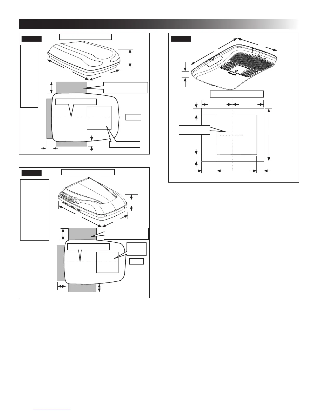
FIG. 4
Dimensions Are Nominal
9-1/2″
29″
40″
Roof Opening
Front
Center Line Of Unit
4″
4″
12″
Keep These Areas
Free Of Obstructions
Model
640312
640315
641815
641816
641835
641915
641916
641935
651815
651816
651916
FIG. 5
Dimensions Are Nominal
10-3/8″
29″
40-1/2″
Keep These Areas
Free Of Obstructions
Roof
Opening
Front
Center Line Of Unit
4″
4″
12″
Model
640312C
640315C
641815C & H
641816C & H
641835C & H
641915C
641916C
641935C
651815C & H
651816C & H
651916C
b. Maintain structural integrity.
Otherwise damage to product and/or RV
could occur.
The roof must be designed to support 130
pounds when the RV is in motion. Normally
a 200 lb. static load design will meet this
requirement.
c. Check inside the RV for air distribution box
(hereinafter referred to as "ADB") obstruc-
tions (i.e. door openings, room dividers, cur-
tains, ceiling xtures, etc.). See (FIG. 6).
FIG. 6
23-1/8″
21-1/8″
Dimensions Are Nominal
11-9/16″
11-9/16″
21-1/8″
3-7/16″
2-5/8″
3-7/16″
6″ 2-7/8″
Roof Opening
B. Roof Preparation
1. FIRE OR ELECTRICAL SHOCK
HAZARD. Verify there are no obstacles inside
RV’s roof and/or walls (wires, pipes, etc.). Shut
OFF gas supply, disconnect 120 Vac power from
RV and disconnect positive (+) 12 Vdc terminal
from supply battery BEFORE drilling or cutting
into RV. Failure to obey these warnings could
result in death or serious injury.
Opening Requirements - Before preparing
the ceiling opening, the type of system op-
tions MUST be decided upon. Read all of
the following instructions before beginning
the installation.
2. Carefully mark and cut the required roof opening.
See "B. Roof Requirements" on page (5).
3. Using the roof opening as a guide, cut the match-
ing hole in the ceiling.
4. Maintain structural integrity. Oth-
erwise damage to product and/or RV could oc-
cur.
NEVER create a low spot on RV
roof. Otherwise, water will pool and could cause
a leak.
INSTALLATION INSTRUCTIONS
 Loading...