16
Dip switches are in the "OFF" position
when shipped from the factory except
heat pump and factory installed heat strip
models. On these models the appropriate
dip switch, heat pump or heat strip, is in
the "ON" position from the factory.
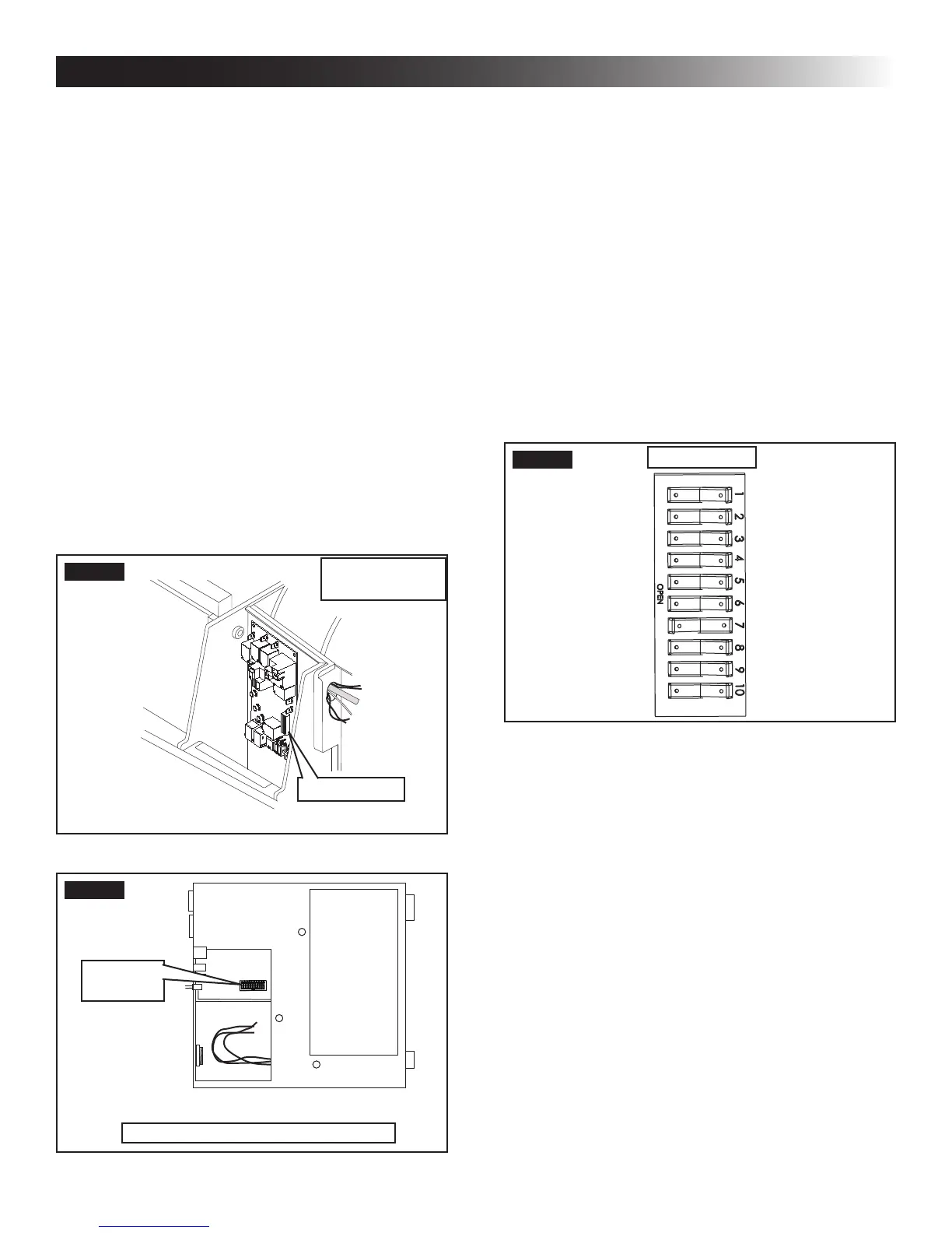
To gain access to the dip switches on mod-
els with board built in, the out side plastic
shroud MUST be removed from the unit.
Next remove the electrical box cover. The
electrical box will be on the curb side of
the RV after installation. See (FIG. 32).
Installations using the electronic control
box the dip switches are visible through
the opening in the electronic control box.
See (FIG. 33).
FIG. 34
Dip Switches
Zone 2
Ext. Stage
Zone 3
Zone 4
Stage
Heat Strip
Heat Pump
Furnace
Dehumidify
Gen Start
a. Ext. Stage - Ext. Stage is not used on this
unit. Leave in the "OFF" position.
b. Zone selection - Each CCC 2 thermostat can
have up to 4 zones. When only one unit is in-
stalled it becomes Zone 1 and no dip switch
setting is required. Each additional unit must
be assigned a zone (2 through 4). Each unit
must have a different zone setting.
c. Stage selection - Stage is not used on this
unit. Leave in the "OFF" position.
d. Heat Strip - On heat strip models the #6
dip switch is in the "ON" position from the
factory. Non heat strip models leave in the
"OFF" position.
e. Heat Pump - On heat pump models the #7
dip switch is in the "ON" position from the
factory. Non heat pump models leave in the
"OFF" position.
f. Furnace - If a Furnace/Aqua heat system
has been connected to this unit, the fur-
nace dip switch must be placed in the "ON"
position.
e. Plug the indoor temperature sensor cable (if
applicable) into the 2 pin matching connec-
tor protruding from the roof opening or the
P4 (white) 2 pin matching connector in the
electronic control box.
f. Connect the previously run Energy Manage-
ment System wires (if applicable) to the yel-
low wires protruding from the roof opening
or the yellow wires in the 6 wire harness at
the electronic control box. The polarity of this
connection does not matter.
g. If an automatic generator start (AGS) kit is
installed, follow installation instructions fur-
nish with AGS kit.
M. (CCC 2 System Only) Conguration
1. Electronic Control Conguration
Depending on the equipment options installed
by the recreational vehicle manufacturer, the ap-
propriate dip switches will need to be switched
to the "ON" position. Placing the switch in the
"ON" position selects that option. See (FIG. 32),
(FIG. 33), (FIG. 34), & (FIG. 35).
FIG. 32
Models With
Board Built In
Dip Switches
FIG. 33
Dip
Switches
Models With Electronic Control Box
INSTALLATION INSTRUCTIONS
 Loading...