19
INSTALLATION INSTRUCTIONS
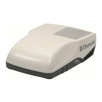
3. Install eight (8) (supplied) wood screws inside
the front, rear, and side doors to secure ADB to
ceiling. See (FIG. 42).
FIG. 42
2 Sheet
Metal Screws
8 Wood Screws
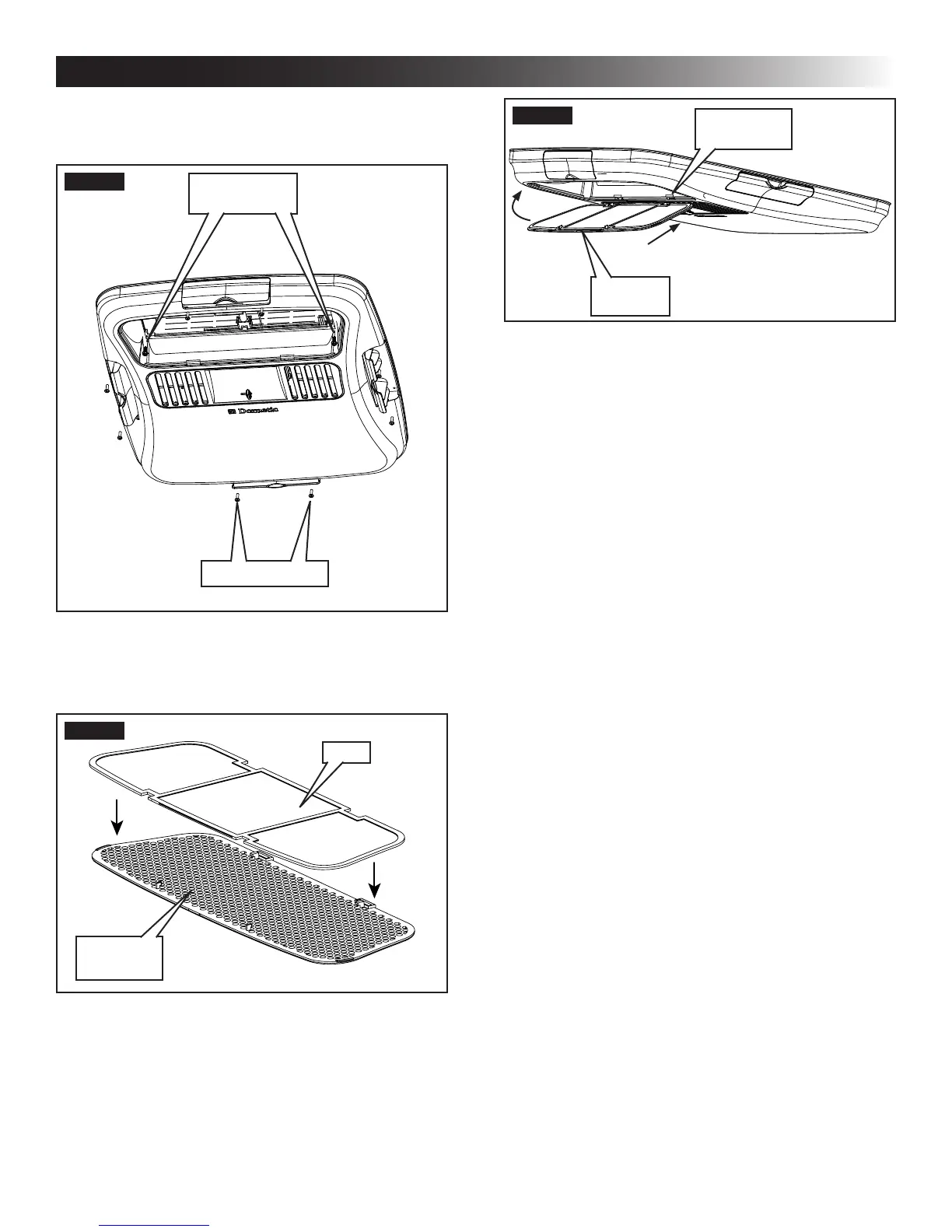
4. Install front and rear doors.
5. Place lter into return air vent grille. It may al-
ready be installed on some units. See (FIG. 43).
FIG. 43
Filter
Return Air
Vent Grille
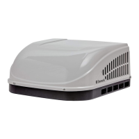
6. Install return air vent grille into the ADB. Slide re-
turn air vent grille tab into slot in ADB and rotate
up and snap in place. See (FIG. 44).
FIG. 44
Slot In ADB
Return
Air Grille
This completes the LCD SZ system installa-
tion. (Proceed to section "P" to complete the
CCC 2 system installation).
7. (LCD SZ System Only) System Checkout
a. Verify that all features of the system work.
See the LCD SZ thermostat Operating In-
structions or User's Guide. Reconnect the 12
Vdc and 120 Vac power supplies. Check fan
speeds, cooling mode, heating mode, and
furnace mode (if connected) operation.
If features do not work, disconnect the 120
Vac and 12 Vdc power supplies and verify
that all wiring is correct.
P. (CCC 2 System Only) Reset & Checkout
1. System Reset
After setting the dip switches in the electronic
control, do a system reset.
a. Reconnect the 12 Vdc and 120 Vac power
supplies.
b. Make sure the CCC 2 thermostat is in the
OFF mode.
c. Simultaneously press the MODE and ZONE
buttons. The LCD will display "IniT" and all
available zones.
d. Release the MODE and ZONE buttons.
e. Press the ON/OFF button to exit system
setup.
f. When a dip switch is turned on after initial
conguration, a system reset will need to be
done before the CCC 2 thermostat will rec-
ognize the updated selection.
2. System Checkout
a. Verify that all features of the system work.
See CCC 2 thermostat Operating Instruc-
tions or User's Guide. Check fan speeds,
cooling mode, heating mode, and furnace
mode (if connected) operation. If features
do not work, disconnect the 120 Vac and 12
Vdc power supplies and verify that all wiring
is correct.
 Loading...