4
INSTALLATION INSTRUCTIONS
A. Table - Unit Data
Model No. Nominal
Capacity
(BTU HR)
Cooling
Electrical
Rating
Compressor
Rated Load
Amps
Compressor
Locked
Rotor
Amps
Fan Motor
Rated Load
Amps
Fan Motor
Locked
Rotor
Amps
Refrigerant
R-410A
(oz)
Minimum
Wire Size*
AC Circuit
Protection
***Installer
Supplied
Minimum
Generator
Size**
1 Unit / 2 Units
459530.70X N/A 120 Vac
60 Hz 1 ph
8.6 50.0 2.5 5.8 20.0 12 AWG
Copper
Up to 24'
15 Amp 2.5 kW / 4.0 kW
459530A70X 8.6 50.0 2.5 5.8 20.0 15 Amp 2.5 kW / 4.0 kW
B59530.71X 8.6 50.0 2.5 5.8 20.0 15 Amp 2.5 kW / 4.0 kW
640310C45X 8.8 56.0 2.6 8.5 20.5 15 Amp 2.5 kW / 4.0 kW
* For wire length over 24 ft., consult the National Electrical Code for proper sizing.
** Dometic Corporation gives GENERAL guidelines for generator requirements. These guidelines come from experiences
people have had in actual applications. When sizing the generator, the total power usage of your RV must be considered.
Keep in mind generators lose power at high altitudes and from lack of maintenance.
*** CIRCUIT PROTECTION: Time Delay Fuse or Circuit Breaker Required.
B. Roof Requirements
● A 14-1/4″ x 14-1/4″ (±1/8″) square opening (hereinafter referred to as “roof opening”) is required for installing this
unit. This opening is part of the return air system of the unit and MUST be nished in accordance with NFPA 1192.
● Roof construction with rafters/joists support frames on a minimum of 16 inch centers.
● Minimum of 1.5 inches and maximum of 6 inches distance between roof to ceiling of RV.
A. Choosing Proper Location For Unit
This unit is specically designed for installation on the roof
of an RV. When determining your cooling requirements, the
following should be considered:
● Size of RV;
● Window area (increases heat gain);
● Amount of insulation in walls and roof;
● Geographical location where the RV will be
used;
● Personal comfort level required.
1. Normal locations-The unit is designed to t over
an existing roof vent opening.
2. Other locations-When no roof vent is available
or another location is desired, the following is
recommended:
a. For one unit installation: The unit should be
mounted slightly forward of center (front to
back) and centered from side to side.
b. For two unit installations: Install one unit 1/3
and one unit 2/3’s from front of RV and cen-
tered from side to side.
It is preferred that the unit be installed on a relatively at
and level roof section measured with the RV parked on a
level surface. See table below for maximum acceptable tilt.
Model
Number
Max
Tilt
459530
459530A
B59530
15°
640310 8°
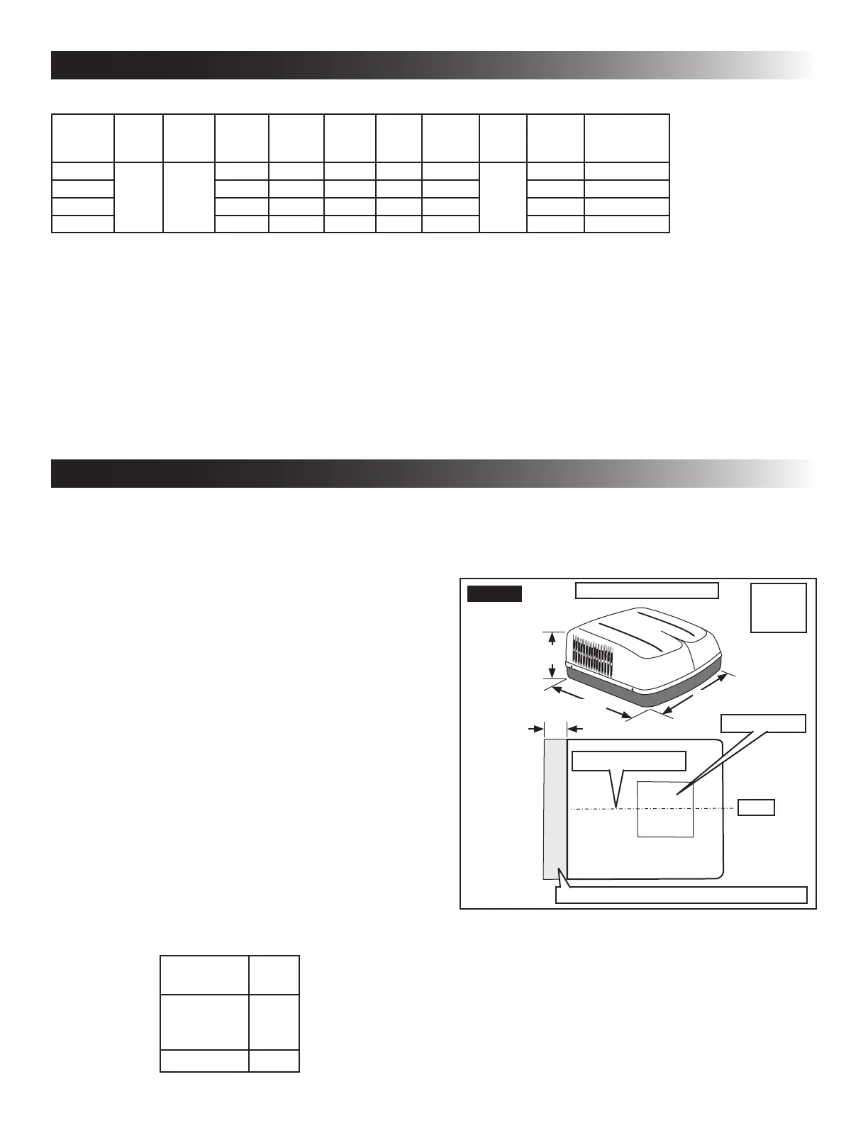
After Location Has Been Selected:
c. Check for obstructions in the area where
unit will be installed. See (FIG. 1), (FIG. 2)
& (FIG. 3).
29-7/8″
34-7/8″
13-1/8″
18″
Front
Dimensions Are Nominal
FIG. 1
Keep This Air Flow Area Free Of Obstructions
Roof Opening
Center Line Of Unit
Model
459530
459530A
SPECIFICATIONS
 Loading...