9
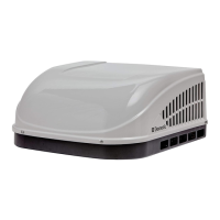
f. Hold the ceiling template up to the roof open-
ing and start each mounting bolt, by hand,
through the ceiling template and up into the
unit base pan. See (FIG. 16) & (FIG. 17).
FIG. 16
Mounting Bolt
Mounting Bolt
Bolt Pattern A, D, E & H Shown
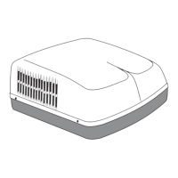
Mounting Bolt Pattern Table - See (FIG. 17)
Model Bolt Location
459530 A, D, E & H
459530A A, D, E & H
B59530 A, D, E & H
640310 B, C, D & G
FIG. 17
A
HG
FE
D
C
B
g. Tighten mounting bolts to
correct torque specications. Overtighten-
ing could damage unit’s base pan or ceiling
template. Not enough torque will allow an in-
adequate roof seal, and could cause a leak.
Tighten all four (4) mounting bolts EVENLY
with in 40 to 50 inch pounds. See (FIG. 16).
F. Wiring System
1. 120 Vac Power Supply Connection
a. ELECTRICAL SHOCK HAZ-
ARD. Make sure 120 Vac power is discon-
nected from RV. Failure to obey this warning
could result in death or serious injury.
b. ELECTRICAL SHOCK HAZ-
ARD. Provide grounding in compliance with
all applicable electrical codes. Failure to
obey this warning could result in death or se-
rious injury.
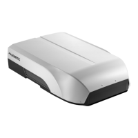
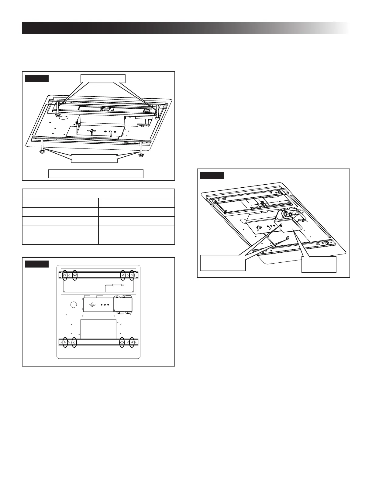
c. Connect white to white; black to black; using
appropriate size connectors. Secure bare
copper wire under grounding screw in junc-
tion box. See (FIG. 18).
FIG. 18
Junction
Box Cover
Junction Box
Cover Screw
d. Tape the connectors to the supply wire to as-
sure they don't vibrate loose.
e. Push the wires into the junction box and in-
stall junction box cover. See (FIG. 18).
INSTALLATION INSTRUCTIONS
 Loading...