5
INSTALLATION INSTRUCTIONS
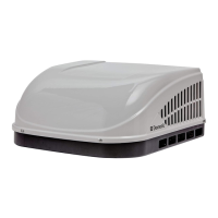
FIG. 2
Dimensions Are Nominal
Roof Opening
Keep This Air Flow Area Free Of Obstructions
Center Line Of Unit
Front
18″
12-7/8″
29-5/8″
27-5/8″
Model
B59530
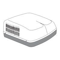
FIG. 3
Dimensions Are Nominal
10-3/8″
29″
40-1/2″
Front
Center Line Of Unit
4″
4″
12″
Model
640310C
Roof Opening
Keep These Air
Flow Areas Free
Of Obstructions
d. Maintain structural integrity.
Otherwise damage to product and/or RV
could occur.
The roof must be designed to support 130
pounds when the RV is in motion. Normally
a 200 lb. static load design will meet this
requirement.
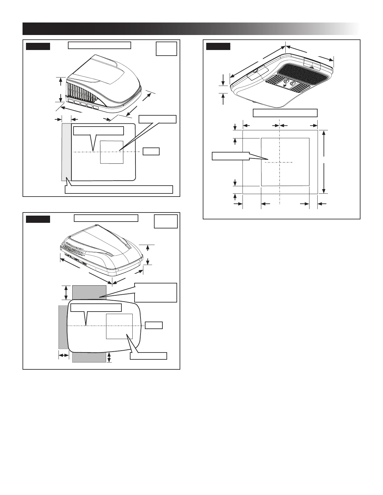
e. Check inside the RV for air distribution box
(hereinafter referred to as "ADB") obstruc-
tions (i.e. door openings, room dividers, cur-
tains, ceiling xtures, etc.). See (FIG. 4).
FIG. 4
23-1/8″
21-1/8″
2-5/8″
Dimensions Are Nominal
11-9/16″
11-9/16″
21-1/8″
3-7/16″
3-7/16″
2-7/8″
6″
Roof Opening
B. Roof Preparation
1. FIRE OR ELECTRICAL SHOCK
HAZARD. Make sure there are no obstacles in-
side RV’s roof and/or walls (wires, pipes, etc.).
Shut OFF gas supply, disconnect 120 Vac power
from RV and disconnect positive (+) 12 Vdc ter-
minal from supply battery BEFORE drilling or
cutting into RV. Failure to obey these warnings
could result in death or serious injury.
Opening Requirements - Before prepar-
ing the ceiling opening, read all of the fol-
lowing instructions before beginning the
installation.
If an existing roof vent opening will NOT
be used a roof opening MUST be cut
through the roof and ceiling of the RV.
This opening MUST be located between
the roof reinforcing members.
2. Roof vent removal
a. Unscrew and remove the roof vent.
b. Remove all caulking compound around
opening.
c. Seal all screw holes and seams where the
roof gasket will be located. Use a good grade
of all weather sealant.
 Loading...