14
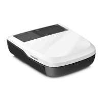
FIG. 27
Attaching Housing Assembly To Strain
Relief Cover With Tongue And Groove
Pliers, Squeeze Squarely & firmly
Between Ribs A & B
Strain Relief Cover 10″ Minimum
Rib A
Locking
Ramp
Locking
Latch
Rib B
Housing Assembly
10. Inspect the connector to ensure the wires have
been properly engaged into the housing assem-
bly contacts. A properly terminated wire is fully
seated into its proper slots with no signicant
bow of the cover. If the wires extend past the
insulation stops the wires must be re-terminated
with a NEW CONNECTOR. Once the cover has
been closed the connector cannot be re-used.
Failure to comply with this procedure may result
in the failure of the connector.
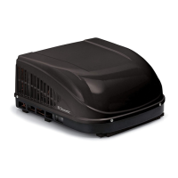
11. Mating and un-mating the completed connector
is illustrated below. See (FIG. 28).
FIG. 28
Housing
Assembly
Strain Relief
Cover
Depress Mating Latch
To Disconnect
To release the connector system, depress both mating
latches at the same time and pull the connectors apart.
To reconnect, simply re-mate the connectors and slide
them together until mating latches lock.
Strain Relief
Cover
Depress Mating
Latch To Disconnect
Housing
Assembly
"Hermaphroditic" Part Mates With Itself
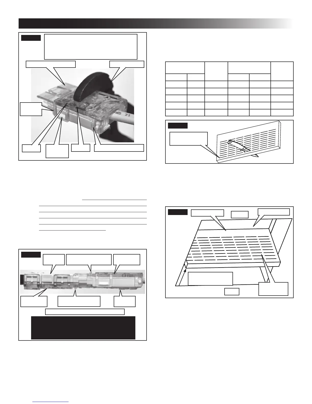
J. Duct Divider Installation
1. Measure the ceiling thickness. See (FIG. 17).
2. Cut away the number of rows as indicated in
table below. See (FIG. 29).
Ceiling
Thickness
# Of
Rows
To Cut
Ceiling
Thickness
# Of
Rows
To Cut
Min. Max. Min Max.
6.0 6.5 0 3.5 4.0 5
5.5 6.0 1 3.0 3.5 6
5.0 5.5 2 2.5 3.0 7
4.5 5.0 3 2.0 2.5 8
4.0 4.5 4 1.5 2.0 9
FIG. 29
Remove Rows
Starting Here
3. Carefully install the duct divider in the roof
opening 5-5/8″ from back of roof opening. See
(FIG. 30).
Foil back faces rear of unit.
FIG. 30
Rear
Base Pan
5-5/8″ From Back
Of Roof Opening
Duct Divider
Front
Black Side
To Front
K. LCD SZ System Low Voltage Wire
Connections
Verify the positive (+) 12 Vdc termi-
nal is disconnected from supply battery. Otherwise,
damage to unit could occur.
1. Plastic Case Electronic Control Kit Systems
Only
a. Plug the supplied freeze control sensor and
the 4 wire harness into their matching con-
nectors in the electronic control box.
INSTALLATION INSTRUCTIONS
 Loading...