17
INSTALLATION INSTRUCTIONS
g. Dehumidify - Dehumidify is not used on this
unit. Leave in the "OFF" position.
h. Gen Start selection - Leave in the "OFF"
position.
i. Install unit electrical box cover and out side
plastic shroud or the electronic control box
cover whichever applies.
j. Repeat this procedure for each additional
zone.
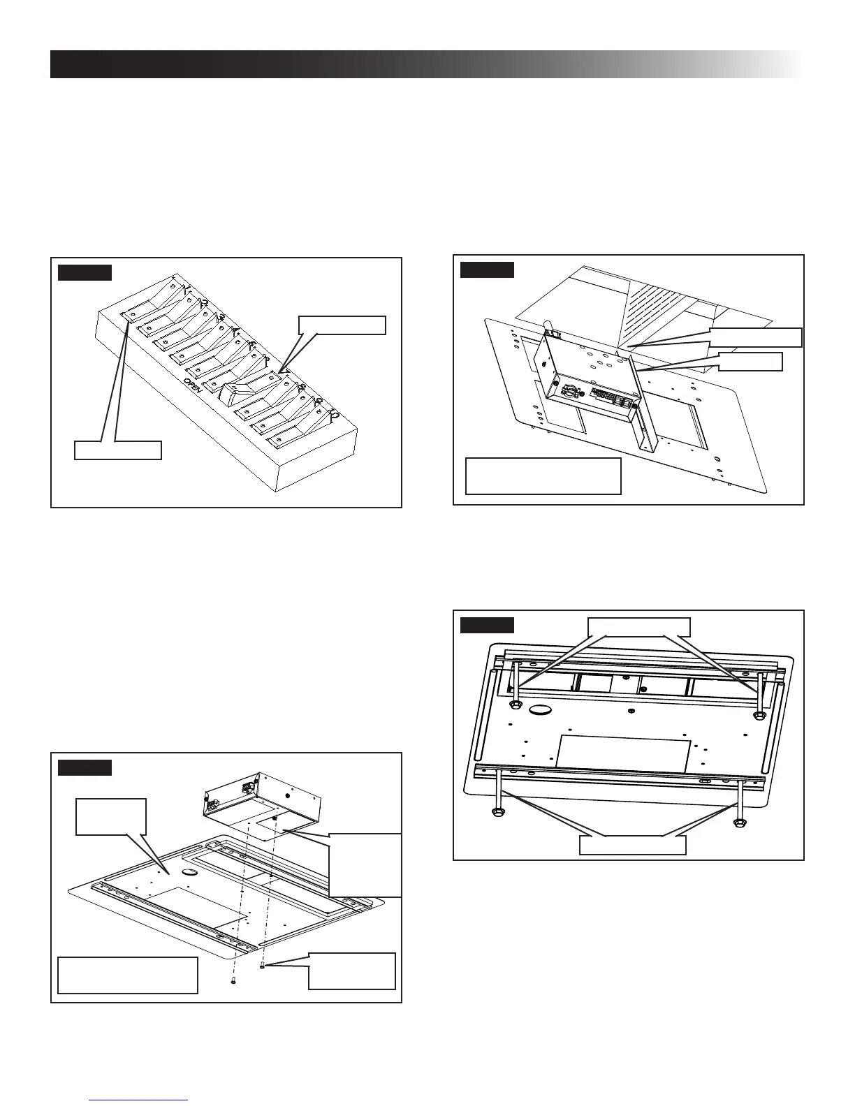
FIG. 35
On Position
Off Position
N. Installing Unit
1. If system includes an electronic control box in-
stall it at this time. Make sure all wiring has been
completed and that the electronic control box
cover has been installed. To secure electronic
control box to ceiling template drive two (2) #6
x 3/8″ (plastic control box) or two (2) #10 x 3/8″
(metal control box) blunt point Phillips head
screws (provided) through the ceiling template
and into holes in the electronic control box. See
(FIG. 36).
FIG. 36
Blunt Point
Screw
Ceiling
Template
Electronic
Control
Box
Metal Electronic
Control Box Shown
2. If your installation includes the optional electric
heat kit, install it at this time. Follow the instruc-
tions with heat kit package for its installation pro-
cedure.
3. Ceiling Template Installation
a. Hold the ceiling template up to the roof open-
ing and line up the channel in the ceiling
template with the previously installed duct
divider. See (FIG. 37).
FIG. 37
Duct Divider
Channel
Model With Electronic
Control Box Shown
b. Hold the ceiling template up to the roof open-
ing and start each mounting bolt by hand,
through the ceiling template and up into the
unit base pan. See (FIG. 38) & (FIG. 39).
FIG. 38
Mounting Bolt
Mounting Bolt
 Loading...