18
Mounting Bolt Pattern Table
See (FIG. 39)
Model Bolt Location
457915 A, D, E & H
B57915 A, D, E & H
B57935 A, D, E &H
459186 A, D, E & H
B59186 A, D, E & H
459196 A, D, E & H
B59196 A, D, E & H
459516 A, D, E & H
B59516 A, D, E & H
459530 A, D, E & H
B59530 A, D, E & H
B59536 A, D, E & H
540315 B, C, F & G
540316 B, C, F & G
541815 B, C, F & G
541816 B, C, F & G
Mounting Bolt Pattern Table
See (FIG. 39)
Model Bolt Location
541915 B, C, F & G
541916 B, C, F & G
551816 B, C, F & G
551916 B, C, F & G
640312 B, C, F & G
640315 B, C, F & G
641815 B, C, F & G
641816 B, C, F & G
641835 B, C, F & G
641915 B, C, F & G
641916 B, C, F & G
641935 B, C, F & G
651815 B, C, F & G
651816 B, C, F & G
651916 B, C, F & G
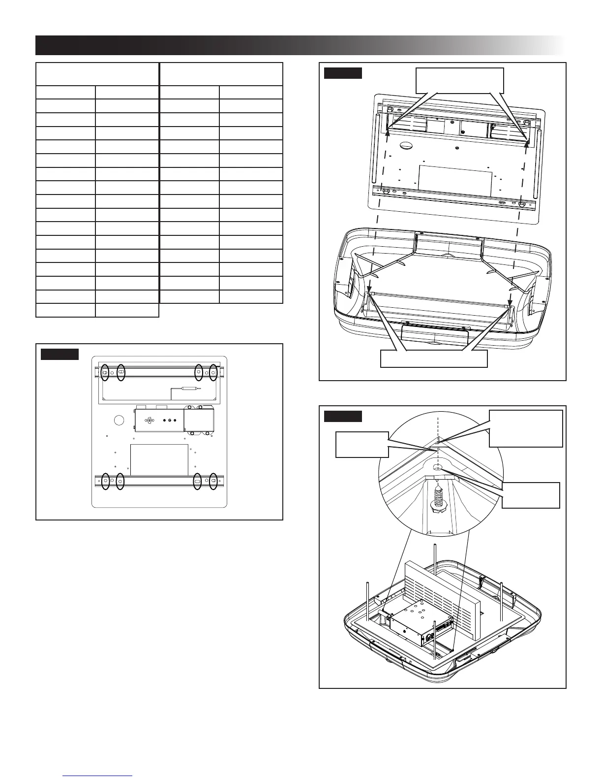
FIG. 39
A
HG
FE
D
C
B
c. Tighten mounting bolts to
correct torque specications. Overtighten-
ing could damage unit’s base pan or ceiling
template. Not enough torque will allow an in-
adequate roof seal, and could cause a leak.
d. Tighten all four (4) mounting bolts EVENLY
with in 40 to 50 inch pounds. See (FIG. 38).
O. Installing ADB
1. Align ADB with ceiling template. See (FIG. 40)
& (FIG. 41).
Front and rear vent doors are supplied
loose. Do NOT install them until all screws
are installed in step 2 & 3.
INSTALLATION INSTRUCTIONS
FIG. 40
ADB Alignment Holes
Ceiling Template
Alignment Holes
FIG. 41
ADB Hole
Alignment
Hole In Ceiling
Template
Hole In
ADB Cover
2. Install two (2) (supplied) sheet metal screws in-
side return air opening to secure ADB to ceiling
template. See (FIG. 42).
 Loading...