34
EN
Operation CapTouch Cabin Control
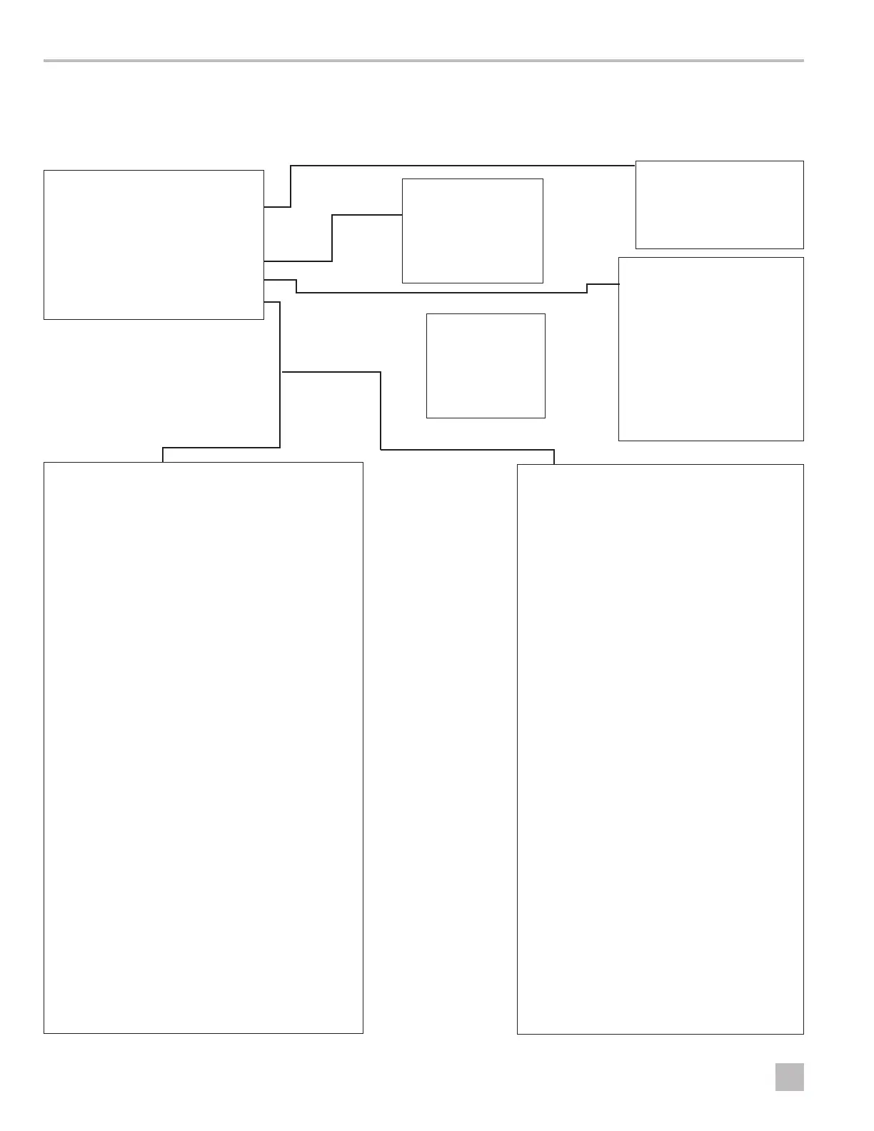
7.8 Navigation Tree
This section shows the menu navigation for the
CapTouch Control.
OPERATING MODES
Cool Mode
Heat Mode
Dehumidification Mode
Aux Heat Mode
Automatic Mode
FAN MODES
Fan Mode
Manual Fan Mode
Fan-Only Mode
Cycled/Continuous Fan Mode
FAULT CODES
IS/- - Inside Sensor Failure
Ar/FL Clean/Replace Filter
LO/AC Low AC Voltage
SAH High Supply Air Temp
LO/SE Sea Water Low Limit
SLP Sleep Mode
HPF High Pressure Fault
LPF Low Pressure Fault
PLF Pump Sentry Fault
IL/- - Loop-Water Sensor
FAULT HELP
Air Sensor Fault
High Pressure Fault
Low Pressure Fault
Low AC Fault
Pump Sentry Fault
DX PROGRAMMABLE PARAMETERS
P-1 High Fan Limit
P-2 Low Fan Limit
P-3 Compressor Staging Time Delay
P-4 Inside Air Temperature Sensor Calibration
P-5 Failsafe Level
P-6 Low Voltage Monitor
P-7 De-Icing Cycle
P-8 Optional Pump Sentry
P-9 Display Brightness Control
P-10 Fahrenheit or Celsius Selection
P-11 Cycle Pump with Compressor
P-12 Reverse Automatic Fan Speeds During Heating
P-13 Cool-Only Mode
P-14 Fan Motor Selection
P-15 Restore Factory Default Settings
P-16 Reserved
P-17 Reserved
P-18 Air Filter Cleaning/Replacement Timer Setting
P-19 Filter Cleaning/Replacement Timer Value & Reset
P-20 CAN Bus Unit ID
P-21 CAN Bus Group ID
P-22 Voltage Calibration
P-23 Set Point Temperature Differential
P-24 Dehumidification Mode Minimum Temperature
P-25 Auto Fan Speed Temperature Differential
P-26 Supply Air High Temperature Limit
P-27 Idle State Delay
P-28 Auxiliary Heat Enable
P-29 Relative Humidity Enable
P-30 Wi-Fi Connectivity
P-31 Seawater Low-Limit Adjustment
P-32 Humidity Sensor Calibration
P-33 Water Inlet Temperature Sensor Calibration
P-34 OAT Sensor Calibration
CW PROGRAMMABLE PARAMETERS
P-1 High Fan Limit
P-2 Low Fan Limit
P-3 Reserved
P-4 Inside Air Temperature Sensor Calibration
P-5 Reserved
P-6 Low Voltage Monitor
P-7 Reserved
P-8 Reserved
P-9 Display Brightness Control
P-10 Fahrenheit or Celsius Selection
P-11 Reserved
P-12 Reverse Automatic Fan Speeds During Heating
P-13 Reserved
P-14 Fan Motor Selection
P-15 Restore Factory Default Settings
P-16 Hydronic Water Valve Forced Open
P-17 Water Temperature Differential
P-18 Air Filter Cleaning/Replacement Timer Setting
P-19 Filter Cleaning/Replacement Timer Value & Reset
P-20 CAN Bus Unit ID
P-21 CAN Bus Group ID
P-22 Voltage Calibration
P-23 Set Point Temperature Differential
P-24 Dehumidification Mode Minimum Temperature
P-25 Auto Fan Speed Temperature Differential
P-26 Supply Air High Temperature Limit
P-27 Idle State Delay
P-28 Auxiliary Heat Enable
P-29 Relative Humidity Enable
P-30 Wi-Fi Connectivity
P-31 Reserved
P-32 Humidity Sensor Calibration
P-33 Water Inlet Temperature Sensor Calibration
P-34 OAT Sensor Calibration
DISPLAY ICONS
Fan Fan Modes
Mode Operating Modes
Mode+Down Fault Log
Mode+Up Programming Menu
Fan+Up Seawater Temp.
Up+Down+Mode Relative Humidity
(DX) Fan+Down Compressor
Run-Time Meter

 Loading...