12 Dräger Polytron 5200 / Dräger Polytron 53X0
Operation
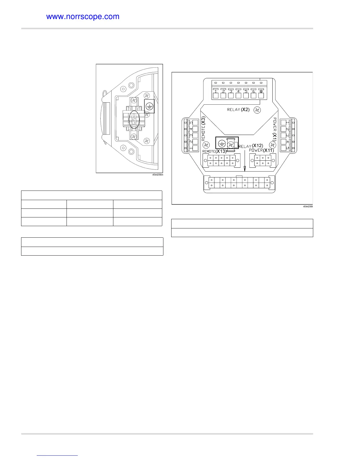
3.3.5 Instrument wiring
3.3.6 Instrument wiring: power only version
Connect the instrument wires
from the feed-through to the
respective terminal in the
e-box.
3.3.7 Instrument wiring: power and relay, or power, relay
and remote sensor version
Plug the connectors of the feed-through into the sockets of the
e-box interface PCB (X11, X12, X13).
.
If a relay option is used, and the default configuration for NO
and NC does not fit for the application, the wiring must be
changed at the relay board,
see Section 5 on Page 22.
z
To rewire the Alarm 1 relay, move the gray wire from A1-
NO to A1-NC.
z
To rewire the Alarm 2 relay, move the blue wire from A2-
NO to A2-NC.
z
To rewire the Fault relay, move the violet wire from FLT-
NO to FLT-NC.
z
The wires to A1-C, A2-C and FLT-C should not be moved.
After all connections are made, swing instrument onto e-box
(ensuring that no wires are pinched and the seal is not compro-
mised) and tighten all four screws with correct torque see
Section 8.5 on Page 24
Solid Oval (Power Only)
Terminal 1 (top) Terminal 2 Terminal 3
V + V - 4 to 20 mA Signal
Red Black Brown
Rectangle (Ground Lug Connection)
Connect ground wire from d-box to ground lug connection
Rectangle (Ground Lug Connection)
Connect ground wire from d-box to ground lug connection

 Loading...