Operation
Dräger Polytron 5200 / Dräger Polytron 53X0 13
3.4 Connecting the instrument to a controller
from Dräger
For hook-up information, please refer to the Instructions for
Use included with the Dräger controller (e.g. Regard, Quad
-
Gard).
3.4.1 Electrical connections at the controller
Connect the shield of the wires to the instrument earth ground
of the controller (e.g. chassis, ground busbar, etc.)
3.5 Normal operation
z
Switch power supply on.
The instrument will go through a start-up sequence (LCD / LED
test, software version, and initialization) and start the warm-up
period. The display shows
and the instrument emits the maintenance signal on the analog
output see Section 4.2 on Page 20. After the warm-up period,
the instrument goes into normal operation.
Pressing the Down arrow during the warm-up period will dis-
play the current sensor selection for example SNR dd.
Pressing the Up arrow will exit the function.
Changing the sensor selection during warm-up will cause
Cycling the power will initialize the instrument to accept the
change. All configurations must be checked, and the instru-
ment must be calibrated.
3.5.1 Analog signals
The current output of the instrument during normal operation is
between 4 and 20 mA and is proportional to the detected gas
concentration.
Polytron 5000 uses different current values to indicate various
modes of operation, see Section 8.3 on Page 24. This follows
the NAMUR NE43 standard.
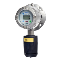
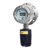
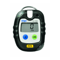
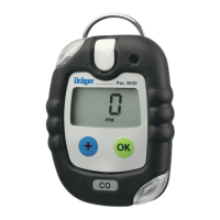
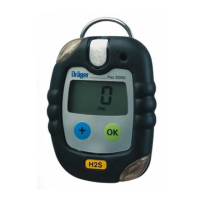
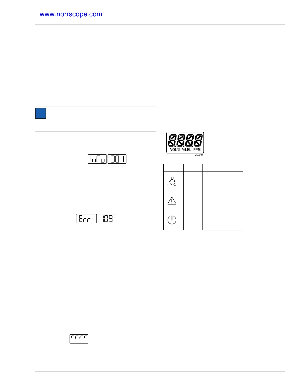
3.5.2 The display and LEDs
In normal operation, the display shows the measured gas con-
centration and unit of measurement. The green LED is lit.
The following special symbols may also be displayed:
{ when the measuring range of the sensor has been
exceeded
{
for the DD and LC sensor an overrange has to be ac-
knowledged with OK.
{
when a fault has been detected the display toggles
between ‘Err’ and a number and the yellow LED is lit,
see Section 4.2 on Page 20
If the optional relay board is installed:
{
when the first alarm has been triggered the red LED
blinks in single mode
{
when the second alarm has been triggered the red LED
blinks in double mode
If an alarm is acknowledgeable, and it is acknowledged, the
blinking of the red LED changes to steady lit and remains lit
until the alarm condition is not present any more,
see
Section 3.7.10 on Page 17.
The segments of the display and LED symbols.
NOTICE
Before leaving the instrument for normal operation,
check the configuration and calibration for the proper
settings.
i
i
Symbol LED Description
Red Alarm Triggered
Yellow Fault / Warning
Green
Power ON
Normal Operation
 Loading...