PowerSeries Neo Installation Guide
Safety Instructions for Service Personnel
Warning: When using equipment connected to the telephone network, always follow the
basic safety instructions provided with this product. Save these instructions for future
reference. Inform the end-user of the safety precautions that must be observed when
operating this equipment.
Before Installing The Equipment
Ensure your package includes the following items:
l Installation and User manuals, including the SAFETY INSTRUCTIONS.
READ and SAVE these instructions!
Follow all WARNINGS AND INSTRUCTIONS specified within this
document and/or on the equipment.
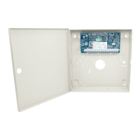
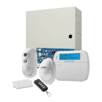
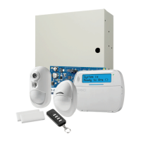
l HS2016/HS2016/2032/2064/2128 alarm controller
l Power Supply, direct plug-in
l Mounting hardware
Selecting A Suitable Location For The Alarm Controller
Use the following list as a guide to find a suitable location to install this equipment:
l Locate near a telephone socket and power outlet.
l Select a location free from vibration and shock.
l Place alarm controller on a flat, stable surface and follow the installation
instructions.
Do NOT locate this product where people may walk on the secondary circuit
cable(s).
Do NOT connect alarm controller to electrical the same circuit as large
appliances.
Do NOT select a location that exposes your alarm controller to direct
sunlight, excessive heat, moisture, vapors, chemicals or dust.
Do NOT install this equipment near water. (e.g., bath tub, kitchen/laundry
sink, wet basement, near a swimming pool).
Do NOT install this equipment and accessories in areas where risk of
explosion exists.
Do NOT connect this equipment to electrical outlets controlled by wall
switches or automatic timers.
AVOID interference sources.
AVOID installing equipment near heaters, air conditioners, ventilators, and
refrigerators.
AVOID locating equipment close to or on top of large metal objects (e.g., wall
studs).
See "Locating Detectors and Escape Plan" on page 20 for information on locating smoke
and CO detectors.
SAFETY Precautions Required During Installation
l NEVER install this equipment and/or telephone wiring during a lightning
storm.
l NEVER touch uninsulated telephone wires or terminals unless the telephone
line has been disconnected at the network interface.
l Position cables so that accidents can not occur. Connected cables must NOT
be subject to excessive mechanical strain.
l Use only the power supply provided with this equipment. Use of unau-
thorized power supplies may cause damage.
l For direct plug-in versions, use the transformer supplied with the device.
WARNING: THIS EQUIPMENT HAS NO MAINS ON/OFF SWITCH. THE PLUG OF
THE DIRECT PLUG-IN POWER SUPPLY IS INTENDED TO SERVE AS THE
DISCONNECTING DEVICE IF THE EQUIPMENT MUST BE QUICKLY
DISCONNECTED. IT IS IMPERATIVE THAT ACCESS TO THE MAINS PLUG AND
ASSOCIATED MAINS SOCKET/OUTLET IS NEVER OBSTRUCTED.
IMPORTANT NOTE FORINTERNATIONALMARKET (EU,
AUS, NZ)!
This equipment is stationary-fixed and must be installed by Service
Persons only (Service Person is defined as a person having the appropriate
technical training and experience necessary to be aware of hazards to
which that person may be exposed in performing a task and of measures to
minimize the risks to that person or other persons). It must be installed and
used within an environment that provides the pollution degree max 2, over
voltages category II, in non-hazardous, indoor locations only. When using
equipment connected to the mains and/or to the telecommunication
network, there are basic safety instructions that should always be
followed. Refer to the safety instructions provided with this product and
save them for future reference. To reduce the risk of fire, electric shock
and/or injury, observe the following: Do not attempt to service this product
yourself. Opening or removing the cover may expose you to dangerous
voltage or other risk. Refer servicing to qualified service persons. Never
open the device yourself. Use authorized accessories only with this
equipment. DO NOT leave and/or deposit ANY object on the top of the
cabinet of this equipment! The cabinet as it is installed on the wall is not
designed to support any supplementary weight! Do not spill any liquids on
the cabinet. Do not touch the equipment and its connected cables during an
electrical storm; there may be a risk of electric shock. Never touch
uninsulated wires or terminals unless the equipment has been disconnected
from the mains supply and from the telecommunication network! Ensure
that cables are positioned so that accidents cannot occur. Connected cables
must not be subject to excessive mechanical strain. Do not spill any type of
liquid on the equipment. Do not use the Alarm system to report a gas leak
if the system is near a leak. Do not subject the connected cables to an
excessive mechanical strain. These safety instructions should not prevent
you from contacting the distributor and/or the manufacturer to obtain any
further clarification and/or answers to your concerns.
Installation
Mounting the Enclosure
Locate the panel in a dry area, preferably near an unswitched AC power
source and the incoming telephone line. Complete all wiring before
applying AC or connecting the battery.
Terminal Descriptions
The following terminals are available on the PowerSeries Neo alarm
controller.
Terminal Description
BAT+,
BAT-
Battery terminals. Use to provide backup power and additional current
when system demands exceed the power output of the transformer, such
as when the system is in alarm.
Do not connect the battery until all other wiring is complete.
AC Power terminals.
Connect the battery before connecting the AC. Do not connect the battery
or transformer until all other wiring is complete.
AUX+,
AUX-
Auxiliary terminals. Use to power modules, detectors, relays, LEDs, etc.
(700mA MAX). Connect the positive side of device to AUX+, the
negative side to AUX-.
BELL+,
BELL-
Bell/Siren power (700mA MAX). Connect the positive side of any alarm
warning device to BELL+, the negative side to BELL-.
RED, BLK,
YEL, GRN
Corbus terminals. Use to provide communication between the alarm
controller and connected modules. Each module has four Corbus
terminals that must be connected to the Corbus.
PGM1 to
PGM4
Programmable output terminals. Use to activate devices such as LEDs.
(PGM1, PGM3, and PGM4: 50mA PGM2: 300mA or can be configured
as an input)
Z1 to Z8
COM
Zone input terminals. Ideally, each zone should have one detection
device; however, multiple detection devices can be wired to the same
zone.
EGND Earth ground connection.
TIP, RING,
T-1, R-1
Telephone line terminals.
PCLINK_1 DLS/SA
PCLINK_2 DLS/SA, Alternate Communicator
Corbus Wiring
The RED and BLK Corbus terminals are used to provide power while
YEL and GRN are used for data communications. The 4 Corbus terminals
of the alarm controller must be connected to the 4 Corbus terminals or
wires of each module.
The following conditions apply:
l Corbus should be run with minimum 22 gauge quad, two pair
twisted preferred.
- 2 -
 Loading...