39
NC
NO
Z15
COM
Z16
Z15
COM
Z16
Refer to
instructions on
keypad wiring.
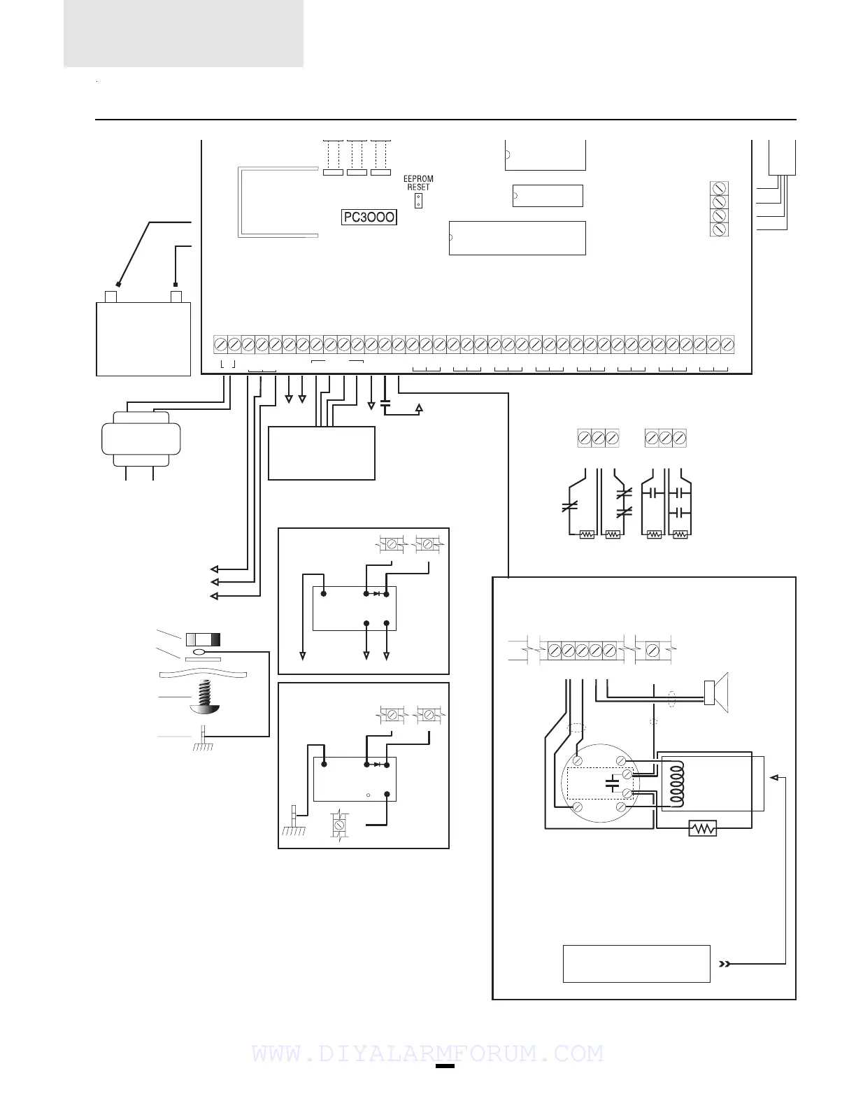
Battery 12V/4.0Ah
GELL-CELL max
battery charge
current is 360 mA.
Battery capacity for
emergency is at
least 4 hours.
Bell\Siren
700 mA max
50 mA max
+12V
-
AUX
+12V
Switched
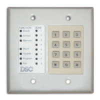
PC3000RK Keypad
(3 Max)
End of line resistor
1KΩ 1/2 Watt
Typical Burglary Zone Connection
Normally
closed
contacts
Normally
open
contacts
Auxiliary
Supply
Outputs
400 mA max
Nut
Washer
Cabinet
Bolt
Ground Rod
NC NO
YEL GRN
BLK RED
WHT
PGM Output Relay
(Keypad [✱],[7])
COM
PGM AUX
Ground Start Circuit
RM-1
BLK RED
WHT
PGM
AUX
RNG
GRN
RM-1
NO
AUX
+ RED
- BLK
BRN
GRY
GRN
RED
AC
4-Wire smoke
power 12 VDC
400mA max
Alarm initiating loop
Resistance 100Ω max
RED
BLK
WHT
GRN
In Out
In Out
ULC listed
4-wire smoke detector
End-of-line resistor
1kΩ 1/2 Watt
AUX
GND
SW
AUX
+
-
BELL
Typical Fire Alarm Zone Connections
NOTE: Smoke detector must be 4-wire ULC listed latching
type (ESL 446C).
To reset smoke detectors - press [✱] then hold down key
[4] for 2-3 seconds.
Bell loop
700 mA max
Horn
FIRE
Smoke detector power
supervision relay (DSC RM-1)
12VDC 35mA
Alarm
Contact
Temperature Range: 0°C-49°C(32°F-120°F)
Maximum Humidity: 85% R.H.
Aux 1A
Bell 5A
Batt 5A
AC Power
CSA Listed
16VAC 40VA
AUX GND
SW
AUX
RED BLK YEL GRN
FIRE
PGM
OUT
AUX
IN
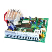
Z1 COM Z2 Z3 COM Z4 Z5 COM Z6 Z7 COM Z8 Z9 COM Z10 Z11 COM Z12 COMZ13 Z14 COMZ15 Z16
KEYPAD+-
BELL
T1
R1
TIP
RNG
RED
BLK
YEL
GRN
HOOKUP DIAGRAMS
WWW.DIYALARMFORUM.COM
 Loading...