Installation and Wiring:
2.6 Assigning Zones to Zone Expanders
7
PC5010 CP-01 Device Ratings (@ 12 V
DC
)
• LCD5500Z/LCD5520Z Keypad: 85 mA
• LCD5501Z Keypad: 45mA
• LCD5501Z32-433 Keypad/Receiver: 260mA (max.)
• PC5100 Addressable Device Interface Module: 40mA
• PC5508Z Keypad: 80 mA
• PC5516Z Keypad: 90 mA
• PC5532Z Keypad: 120 mA
• PC5108 Zone Module: 35 mA
• PC5108L Downlook Interface: 60 mA
• PC5132 Wireless Module: 125 mA
• PC5200 Output Module: 20 mA
• PC5204 Output Module: 20 mA
• PC5208 Output Module: 50 mA
• PC5320 Multiple Receiver Interface Module: 55mA
• Escort5580(TC) Module: 150 mA
• PC5400 Printer Module: 65 mA
• PC5700 Fire Module: 150 mA
• PC5904 Central Station Talk/Listen Module: 175mA
• PC5936 Audio Interface Module: 65 mA
• PC5937 Audio Port Expansion Module: 5mA
• PC5921 Intercom Audio Station: 20 mA
• PC5921 EXT Door Box Audio Station: 20 mA
• PC5921 EXT/R Door Box Audio Station: 35 mA
• DLM-4L v1.0: 180 mA
• T-Link module: 150mA
System Outputs (all 12 V
DC
)
Other Devices
Read the manufacturer’s literature carefully to determine
the maximum current requirement (during activation or
alarm) and use this value for loading calculations. Do not
allow connected devices to exceed the system capabilities
during any possible operational mode.
2.6 Assigning Zones to Zone Expanders
The main panel contains zones 1 to 8. Additional zone
expanders may be added to increase the number of zones
on the system. Each zone expander consists of one group
of 8 zones. Each module must be set to assign the specific
zones to the expander. To do this, set the jumpers located
on the expander to the proper settings (see chart below).
NOTE:
PC5108 v1.0 and lower, PC5108L, PC5700, and
PC5720 each enroll as two expander modules.
NOTE:
Before a zone expander will work properly, you
must set the jumpers so the panel can determine the correct
zone assignment.
NOTE:
It is not recommended to use PC5108 v1.x and v2.x
simultaneously on the same PC5010 CP-01.
The following are the jumper settings for different zone
assignments for PC5108 v2.0 modules. If you need to
enroll PC5108 v1.0, PC5108L or PC5700 modules, refer to
the appropriate module
Installation Sheet
for the correct
jumper settings.
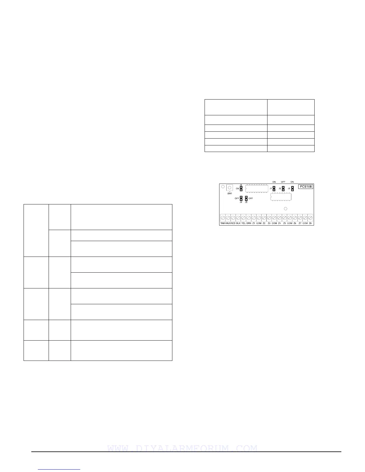
The following is a diagram of the PC5108 zone expander
modules and where the jumper switches are located. Refer
to the
Installation Instructions
for the module for more
information.
NOTE:
Only jumpers J1, J2, and J3 determine the zone
assignment for the module.
2.7 Keypad Assignment
There are 8 available slots for keypads. LED and
LCD5501Z keypads by default are assigned to slot 1. The
LCD5500Z/LCD5520Z is assigned by default to slot 8.
Keypads can each be assigned to a different slot (1 to 8)
which offers two advantages. The panel can supervise the
keypad connection to indicate a Trouble condition if it is
removed. Also keypads can be assigned to operate a spe-
cific partition, or to operate as a global keypad.
How to Assign Keypads
NOTE:
All keypad assignment must be done at each keypad
on the system. When using LCD5500Z/LCD5520Z keypads,
one keypad must remain in slot 8. Do not assign more than
one keypad to the same slot.
NOTE:
To assign a keypad to a slot and select the partition
it will operate, enter the following:
1. Enter Installer Programming
2. Press [000] for Keypad Programming
3. Press [0] for Partition and Slot Assignment
4. Enter a two digit number to specify the partition and slot
assignment.
1st digit enter 0 for Global operation, or
enter 1-2 for partitions 1-2
2nd digit enter 1 to 8 for Slot Assignment
5. Press the [#] key twice to exit programming.
6. Continue this procedure at each keypad until all have
been assigned to the correct slot and partition.
PC5010
CP-01
VAUX: 550 mA.
Subtract the listed rating for each keypad, expan-
sion module and accessory connected to VAUX or
Keybus. NOTE: The maximum AUX capacity
for 24-hr standby is 420mA.
BELL: 700 mA.
Continuous Rating.
3.0 A.
Short Term. Available only with standby battery
connected.
PC5200 VAUX: 1.0 A.
Continuous Rating. Subtract for each device con-
nected.
3.0 A.
Short Term. Available only with standby battery
connected.
PC5204 VAUX: 1.0 A.
Continuous Rating. Subtract for each device con-
nected.
3.0 A.
Short Term. Available only with standby battery
connected.
PC5208 VAUX: 250 mA.
Subtract for each device connected. Subtract the
total load on this terminal from the PC5010 CP-
01 VAUX/Keybus output.
PC5108 VAUX: 100 mA.
Subtract for each device connected. Subtract the
total load on this terminal from the PC5010 CP-
01 VAUX/Keybus output.
Module Jumpers
System Zones
Assigned
J1 J2 J3
ON ON ON Zones disabled
OFFONONZones 09 - 16
ON OFF ON Zones 17 - 24
OFF OFF ON Zones 25 - 32
WWW.DIYALARMFORUM.COM
 Loading...