DUPLOMATIC E.M.DDC4-400V/RK RELEASE 1.9 07-09
EM DDC4-400-RK-0709gb.doc 13
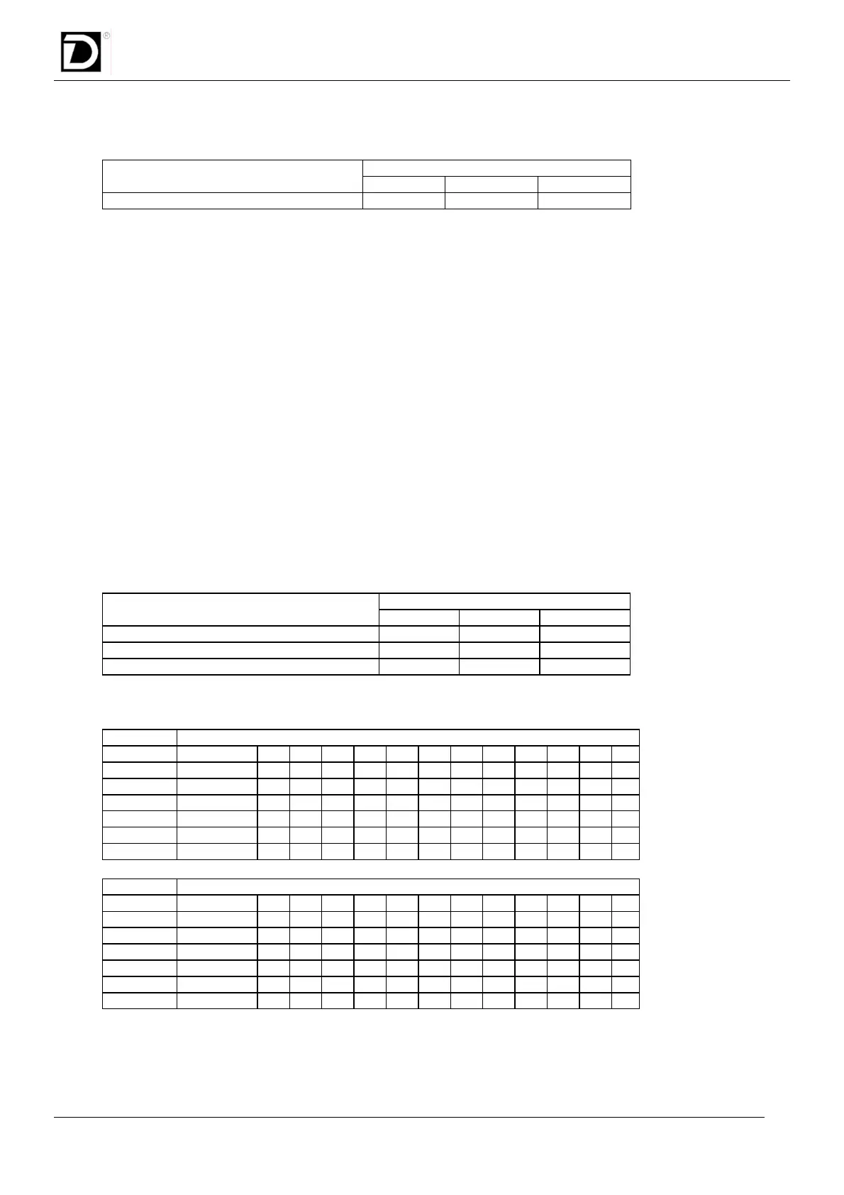
OPERATING FUNCTION N°0: EMERGENCY / RESET
INPUTS OPERATING FUNCTION N°0
MODE01 MODE02 MODE03
Emergency/reset
0 0 0
This operating function has two purposes:
1) Stop all turret movement (EMERGENCY).
2) Acknowledge all alarms, if they are present (RESET).
It must stay on for more than 30 ms to be read by the control unit. It isn’t necessary to carry out a RESET to go
into or out operating function. Meanwhile, the transition from one operating function to the other could generate
a transitory condition that can be detected as an emergency request.
The INDEX signal goes low after a RESET.
The alarm output will be cleared changing from operating function N°0 to another operating function (e.g.
Automatic).
In any case, after changing from mode 0 to any other mode, it is necessary to wait 800 ms before any
variation of PSTART signal.
OPERATING FUNCTION N°1,2,3: AUTOMATIC
These operating functions are normally used to drive the turret.
Just set the code of the position required, give the start signal and the turret will automatically reach the
position.
1. Clear all alarms (if present);
2. Set an automatic function:
INPUTS OPERATING FUNCTION N°1,2,3
MODE01 MODE02 MODE03
Automatic with shortest path search
1 0 0
Automatic CW
0 1 0
Automatic CCW
1 1 0
3. Set the position code: (use PBIT16 only for turrets with 16 tools or more).
POSITION
CODE Zero Cycle 1 2 3 4 5 6 7 8 9 10 11 12
PBIT01
0 1 0 1 0 1 0 1 0 1 0 1 0
PBIT02
0 0 1 1 0 0 1 1 0 0 1 1 0
PBIT04
0 0 0 0 1 1 1 1 0 0 0 0 1
PBIT08
0 0 0 0 0 0 0 0 1 1 1 1 1
(PBIT16)
0 0 0 0 0 0 0 0 0 0 0 0 0
PARITY
0 1 1 0 1 0 0 1 1 0 0 1 0
POSITION
CODE 13 14 15 16 17 18 19 20 21 22 23 24
PBIT01
1 0 1 0 1 0 1 0 1 0 1 0
PBIT02
0 1 1 0 0 1 1 0 0 1 1 0
PBIT04
1 1 1 0 0 0 0 1 1 1 1 0
PBIT08
1 1 1 0 0 0 0 0 0 0 0 1
(PBIT16)
0 0 0 1 1 1 1 1 1 1 1 1
PARITY
1 1 0 1 0 0 1 0 1 1 0 0
4. Set PSTART for give the confirmation of the movement within 5 s.
(It must stay ON for more than 30 ms).