11
Specifications
Eaton 1250W / 1500W / 1800W Inverter Operation and Installation Guide IM SP180164 / Rev D www.eaton.com
Table 12. DC Output Voltage
O/P voltage VDC (tolerance +/- 0.2Vdc)
Battery type setting Bulk Absorption Float
Fixed 13.5 13.5 13.5 13.5
Flooded 14.4 14.4 13.5
Gel 14.2 14.2 13.8
AGM 14.3 14.3 13.4
Table 13. DC Output Current
Maximum DC output current (Adc)
Model Setting1 Setting2 Setting3 Setting4 Setting5
12-110-1800-B4 2 +/- 0.5 5 +/- 1 10 +/- 1 20 +/- 2 40 +/- 4
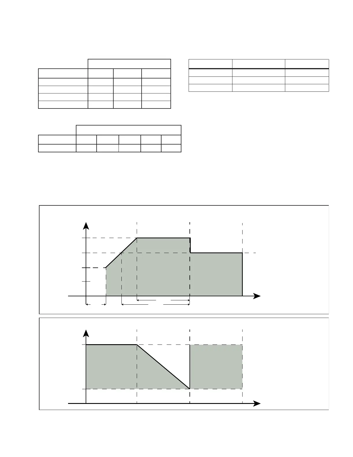
Figure 3. Charge Algorithm
Voltage
Time
Time
Current
Bulk stage Absorption stage Float stage
Bulk stage Absorption stage Float stage
Absorption voltage
Float voltage
10V
5V
Charge current
setting
Float current
Maximum charge
current setting
15 min
8 hrs max
5 hrs max
NOTE:
If an external DC load is
connected to the battery and
it drains the battery down to
12.8Vdc, the charger will
start a new bulk stage.
NOTE:
During the float stage, the
charger will provide up to the
maximum set charge current
to compensate for an
external DC load on demand.
Table 14. Fan On/Off Setting
Parameter Fan on Fan off
Load > 500W < 200W
Extrusion temperature > 60°C < 55°C
Rectifier diode > 70°C < 60°C
Display panel indicators / switches
• Power On/Off momentary switch
• ‘Select’ momentary switch
• 3 x 7-segment LED display
• ‘STATUS’ LED (tri-color)
• ‘Battery Voltage’ LED (Green)
• ‘Battery Current’ LED (Green)
• ‘Output Power’ LED (Green)
• Remote communication cable, 6-wire, 25ft long
 Loading...