19
Connect the AC input wires (optional for AC input)
Eaton 1250W / 1500W / 1800W Inverter Operation and Installation Guide IM SP180164 / Rev D www.eaton.com
Connect the AC input wires (optional for AC input)
Wire routing guidelines
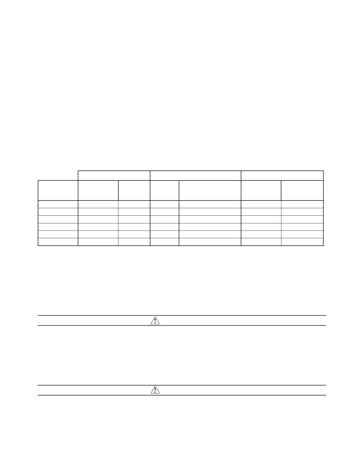
See Table 19 for suggested cable size for DC input connections and fuse ratings required at the battery end of the positive
DC input cable.
Build the cables before rough fitting them to the vehicle. Note any points that will require special attention to avoid chafing
or exposure to heat sources. Eliminate potential trouble areas by installing clamps, protecting wiring harnesses with plastic
wrap, and installing grommets in feed through holes.
To prevent chafing, cables, plumbing, and installed equipment should not come into hard contact with each other. Because
the bodywork and structure can flex during operation, at least a quarter inch clearance is advised between cables and nearby
equipment. Do not route cables in high heat areas without adequate thermal protection. Avoid exposure to chemical damage
by using protective conduit or wrap.
Torque DC input cable fasteners to 12.2 -13.6 Nm (9-10 ft lbs).
Torque Chassis Ground cable fastener to 6.6 – 7.3 Nm. (5-5.5 ft lbs).
Table 19.
DC Input AC Input AC Output
Model
Min Wire Size
(AWG)
Required Fuse
(Amp)
Min Wire
Size (AWG)
Branch circuit protection
required - recommended fuse
(Amp)
Min Wire Size
(AWG) Notes
12-110-1250y 2 150 14 20 14 1, 3
12-110-1250-Bxy 2 150 12 20 14 1, 2, 3
12-110-1500y 2 175 14 20 14 1, 3
12-110-1500-Bxy 2 175 12 20 14 1, 2, 3
12-110-1800y 1 200 12 30 12 1, 3
12-110-1800-Bxy 1 200 10 30 12 1, 2, 3
1. AC output fuse is not required as all models feature a 20A output breaker
2. Suffix ‘x’ defines battery charger setting: 0, disabled; 4, 40A charger enabled
3. Suffix ‘y’ defines input under-voltage setting: L, 11.8V; M, multi-select; H, 12.1V
Ensure the GFCI is in its proper location and install the front panel back on to the inverter.
AC wiring WITH an inverter subpanel –
In this wiring configuration, the AC input to the inverter comes from a main AC panel with its own input circuit breaker. The
AC output is then routed to a separate inverter subpanel with a dedicated circuit breaker attached.
IMPORTANT
It is important to note the generator must have its own neutral bonded to ground. If the generator’s neutral is not bonded to
ground, a bonding jumper must be installed. The input AC panel and the inverter subpanel must not have a permanent neu-
tral to ground bond installed.
AC wiring WITHOUT an inverter subpanel
This wiring configuration has the AC input to the inverter coming from an AC source directly. The AC must then be protected
by a branch AC breaker or fuse, see Table 19 for fuse recommendations. The AC output is routed to the main AC panel which
is protected by AC circuit breakers.
IMPORTANT
It is important to note the generator must have its own neutral bonded to ground. If the generator’s neutral is not bonded to
ground, a bonding jumper must be installed. In this case, the main AC panel must not install a permanent neutral to ground
bond.
 Loading...