Page 30 I.B. 3A74792H08
Effective 09/2014
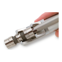
The switchgear compartment mounted secondaries are
of a movable carriage design. Once the circuit breaker is
in the TEST position, the structure mounted secondary
plug carriage can be manually unlatched and pulled
forward until mating with the circuit breaker mounted
male plugs. To disengage the secondary plugs from the
TEST position, simply push the carriage to the rear.
Secondary connections are automatically engaged or
disengaged when moving into or out of the CONNECTED
position.
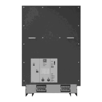
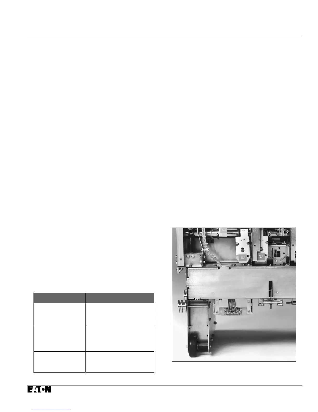
5-4.3 SECONDARY TERMINAL BLOCKS
VCP-WR fixed circuit breakers are supplied with 2 12-
point screw type secondary control terminal blocks for
simple secondary control access. A number of points are
used for breaker operation with a number of spare
contacts for customer use. The terminal blocks are
located at the lower front of the circuit breaker (5-9). Two
additional terminal blocks are available for a second
auxiliary switch.
5-4.4 UNDERVOLTAGE TRIP DEVICE
The undervoltage trip device for VCP-W and VCP-WR
circuit breakers is an electromechanical device that
operates to open the circuit breaker at 30% or less of the
voltage rating of the trip coil. The device does not open
the circuit breaker at values above 60% of the volt-age
rating of its trip coil. It may operate, however, to open the
circuit breaker when the voltage across the trip coil is
greater than 30%, but less than 60% of the volt-age
rating of its trip coil. The circuit breaker can be closed as
long as the voltage to the trip coil is maintained at 85% or
above the rated level. The undervoltage trip device is
available only as an instantaneous type with rated
voltages of 48VDC, 1 25VDC, 250VDC 120VAC and
240VAC.
Table 5.1 Circuit Breaker Timing
Event Milliseconds (maximum)
Closing Time
(From Initiation of Close
Signal to Contact Make)
75
Opening Time
(Initiation of Trip Signal
to Contact Make)
45
Reclosing Time
(Initiation of Trip Signal
to Contact Make)
190
For a basic understanding of the operation of the
under-voltage trip device refer to the specific items
identified in Figure 5-10 and the following operation
description.
1. With the circuit breaker closed and sufficient
voltage on the Undervoltage Trip Device coil, the
moving clapper (1) is held to the stationary yoke
(2) by the magnetic force produced by the coil (3)
against the extension springs (4) pulling the
moving clapper apart from the yoke.
2. The moving clapper is connected to the
mechanism Trip D Shaft Lever (5) by a slotted
link (6).
3. When the voltage to the Undervoltage Trip Coil
goes down as described earlier, the extension
springs force overcomes the reduced magnetic
force and pulls the moving clapper up. The slotted
link in turn upsets the Trip D Shaft and the circuit
breaker trips open.
4. As the circuit breaker opens, the reset lever (8)
connected to the pole shaft lever (7) operates to
reset the moving clapper. As long as the circuit
breaker remains open, the reset lever holds down
the moving clapper to the yoke.
Figure 5-8 Secondary Plug Shown Mounted Lower
Left Drawout Circuit Breaker
 Loading...