I.B. 3A74792H08 Page 31
Effective 09/2014
5. When the circuit breaker closes, the reset lever moves
away from the moving clapper. If the Under-voltage
Trip Device coil has at least 85% of the rated voltage
applied, the moving clapper is held to the yoke by the
magnetic force, even though the reset lever has
moved up.
5-5 INTERLOCKS AND INTERFACING
Refer to Paragraph 4-9 of this manual for detailed
information concerning circuit breaker interlocks and their
interfacing with a switchgear structure compartment. In
addition, refer to the instruction manual supplied with
the switchgear assembly. Customers are responsible for
providing VCP-WR interfaces.
5-6 LEVERING MECHANISM (VCP-W ONLY)
The purpose of the levering mechanism is to move the
drawout VCP-W circuit breaker into and out of the
CONNECTED position within the assembly structure.
The levering mechanism used to move the circuit breaker
is a minimum effort recirculating ball drive design, and is
part of the assembly structure cradle. For additional
information concerning the levering mechanism, refer to
the instruction manual supplied with the switchgear
assembly. Paragraph 4-8.1 of this manual provides
details concerning the use of the levering mechanism to
move the circuit breaker into and out of the CONNECT-
ED position within the assembly structure.
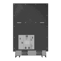
Figure 5-9 Secondary Terminal Blocks Shown Mounted
Bottom Front Fixed Circuit Breaker (Shown With
Terminal Blocks for Second Auxiliary Switch)
5-7 OPERATIONS COUNTER
All circuit breakers are equipped with a mechanical
operations counter. As the circuit breaker opens, the
linkage connected to the pole shaft lever advances
the counter reading by one (Figure 3-8).
5-8 GROUND CONTACT
The ground contact used with the drawout VCP-W
circuit breaker is an assembly of spring loaded fingers
providing a disconnectable means for grounding the
circuit breaker chassis, after it has been inserted into
a switchgear structure. The ground contact is located
on the lower left portion of the truck chassis. An
extension of the switchgear ground bus is secured to
the cell floor in such a position to engage the ground
contact automatically, when the circuit breaker is
moved into the DISCONNECT/TEST position. It
remains engaged in all other circuit breaker positions
within the cell. The lever is supplied on the VCP-WR
breaker, but the customer is responsible for supplying
the proper interface.
5-9 MOC AND TOC SWITCH OPERATIONS
A MOC operator integral to the circuit breaker
engages an operating lever of the Mechanism
Operated Cell Switch (MOC) located in the switchgear
cell. This MOC operator permits the contacts of the
MOC Switch to be correlated with the circuit breaker’s
contact position.
The cell mounted Truck Operated Cell Switch (TOC)
is operated by movement of the circuit breaker truck
into or out of the CONNECTED position with the
VCP-W only.

 Loading...