I.B. 3A74792H08 Page 41
Effective 09/2014
The recommendations and information contained
herein are based on Eaton experience and judgment,
but should not be considered to be all-inclusive or
covering every application or circumstance which may
arise. If further information is required, you should
consult Eaton.
Testing Procedures: Assuming that the breaker is
safely pulled out to the Test/Disconnect position in the
enclosure or placed on the workbench, follow this
procedure to perform the CloSure
TM
Test. For further
instructions on disconnecting the circuit breaker consult
Section 4 of this manual. If the enclosure is equipped
with the MOC operating in the test position also, make
certain that the MOC is connected to operate.
Step 1 - On the front cover identify the status indicators.
MAKE SURE THE CLOSING SPRING STATUS
INDICATES
“Discharged” AND THE MAIN
CONTACT INDICATOR SHOWS “Open” (Figure 6-7).
Step 2 - Remove the circuit breaker front cover. Be sure
to save the original fasteners for reassembly.
Step 3 - Cut a piece of one inch wide drafting/masking
tape approximately 8 to 10 inches long.
Step 4 - Place the tape around the cam starting from the
bottom up. Make certain that the tape adheres well to
the cam surface. (See Figures 6-8, 6-9 and 6-10).
Step 5 - Mount the transparent CloSure
TM
Test Tool
with two bolts and washers. Refer to Figures 6-21, 6-22
and Table 6.3 for appropriate mounting holes. Hand
tighten the bolts (Figures 6-11, 6-12, 6-21 and 6-22).
Step 6 - A Sanford
®
Sharpie
®
black fine point permanent
marker, item no. 30001, is recommended for this next
step. Place the marker tip in the proper hole (“C”). Refer
to Figure 6-21 and make a heavy mark on the tape as
shown in Figure 6-14.
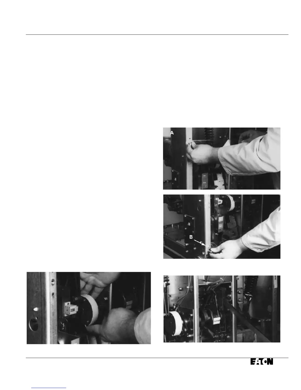
Figure 6-10 Attaching Tape Around to Back of Cam
Step 7 - Charge the closing springs with the
maintenance tool. Continue charging the closing
springs until a “click” is heard and the status indicator
shows
“Charged” (Figure 6-13).
Step 8 - While holding the marker tip on the tape,
close the breaker (Figure 6-14).
Step 9 - Move the marker back and forth horizontally
approximately 15
o in both directions to create a line
on the tape that identifies the closed rest position
(Figures 6-15, 6-21 and 6-17B.
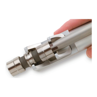
Figure 6-11 AttachingCloSure
TM
Test Tool at Hole “A”
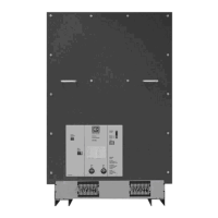
Figure 6-12 Attaching CloSure
TM
Test Tool at HPole “B”
Figure 6-13 Manually Charging Closing Springs
 Loading...