Instruction Book
Effective: November 2017 Page 22
For more information visit: www.Eaton.com IB131016EN
SECTION 4: INSTALLATION AND WIRING
any required barriers used with specific breakers. Any
other barriers required to meet ANSI requirements must
be supplied by the customer. They must be constructed
of an appropriate insulating material, such as thick high
strength, track resistant glassmat polyester or
polycarbonate of appropriate thickness.
4-4 FRONT COVER
The front cover of VCP-T and VCP-TR circuit breakers is
designed such that the customer can choose to have a
closed door or open door design. If a closed door design
is selected, an appropriately sized door cutout can be
provided by the customer to permit access to all front
mounted circuit breaker controls and devices (Figure 3-
10).
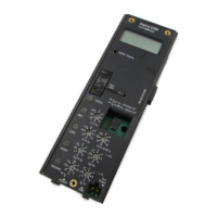
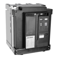
4-5 INSTALLING FIXED CIRCUIT BREAKER
The VCP-TR fixed type circuit breaker differs from the
VCP-T drawout circuit breaker in that it has no levering
device, primary disconnects and secondary umbilical
disconnect (Figure 4-1). In addition, a VCP-TR fixed
circuit breaker does not have a standard feature to hold
the breaker in a trip free position. To ensure the proper
sequence of operation between two or more circuit
breakers, an optional key interlock and/or optional cable
interlock can be used.
4-5.1 FIXED MECHANICAL INTERFACES
The customer is responsible for providing all required
mechanical interfaces to insure that the VCP-TR fixed
circuit breaker is properly installed and applied in a fixed
configuration. This responsibility includes but is not
limited to the following:
1. The circuit breaker must be securely mounted in an
installation capable of supporting the circuit breaker’s
weight. Mounting holes are provided in the bottom pan of
the circuit breaker for use with appropriate mounting
hardware (Figures 1-1, 1-4, and 4-2).
2. Appropriately sized, secured, and braced primary
connections must be provided, whether the connections
take the form of cable or bus bar. Circuit breaker primary
terminals have holes for making bolted horizontal primary
bus connections. Refer to Figures in Chapter 1 for
primary connection details, such as primary spacing and
hole patterns.
4-5.2 FIXED ELECTRICAL INTERFACES
Secondary electrical connections can be made through a
standard secondary disconnect block or an optional
screw type terminal block. Both secondary connection
devices are mounted at the top, front of the circuit
breaker. Secondary contacts are dedicated and
identified. Refer to Figures 5-10 to 5-13 for secondary
connection details.
NOTICE
Refer to the circuit breaker weights in Table 3.1 to
ensure that any table used for inspections is capable
of supporting the circuit breaker.
4-1 INITIAL INSPECTION
Before attempting to use or put a circuit breaker into
service, examine it for loose or obviously damaged parts. In
addition, compare the circuit breaker nameplate with
associated drawings, shipping papers and ordering
information for compatibility. A circuit breaker should also
be operated manually. To check the manual operation of a
circuit breaker, follow the operational procedures outlined
in Section 5.
For fixed breaker applications, an electrical operations
check should be performed after the breaker is
appropriately mounted, secondary wiring completed, and
any appropriate interphase barriers installed. To check
the electrical operation of a circuit breaker, follow the
operational procedures outlined in Section 5.
For drawout breaker applications, an electrical operations
check should be made with the breaker in the TEST
position or by using a “Test Cable” with the breaker out of
its cell. Refer to paragraphs later in this section covering
“Circuit Breaker Positioning” and “Drawout Electrical
Interfaces”. Once familiar with this information, refer to
Section 5 for electrical operation procedures.
4-2 ELECTRICAL CLEARANCES
It is the responsibility of the customer to insure that the
proper electrical clearances are maintained on the circuit
breaker, in the assembly structure, and between the circuit
breaker and its assembly structure. These required
electrical clearances must be in keeping with the
appropriate ANSI standards and the specific BIL
application level. The BIL rating associated with a particular
circuit breaker is clearly indicated on its nameplate located
on the front cover. Also refer to Table 1.1 for circuit breaker
rating details.
4-3 INTERPHASE BARRIERS
ANSI requires specific dielectric performance. It is the
customer's responsibility to insure that all required
interphase barriers are in place on the circuit breaker before
the circuit breaker is placed in service. Appropriately sized
and constructed barriers are supplied with the circuit
breaker. The number and types (vertical or horizontal) of
barriers used with fixed and drawout circuit breakers
depends primarily on the circuit breaker rating. Refer to
Figures 1-1 to 1-6 for
 Loading...