Instruction Book
Effective: November 2017 Page 47
IB131016EN For more information visit: www.Eaton.com
Table 5.3 Shunt Trp Ratings
Control
Voltages
Operational
Voltage Range
Inrush Power
Consumption
Typical
Opening Time
24 Vdc 17-26 250 VA 25 - 38 ms
48 Vdc 34-53 250 VA 25 - 38 ms
110 Vdc 77 - 121 450 VA 25 -
38 ms
125 Vdc 88-138 450 VA 25 - 38 ms
220 Vdc 154-242 450 VA 25 - 38 ms
250 Vdc 175-275 450 VA 25 - 38 ms
110 Vac 77 - 121 Cap. Trip 25 - 38 ms
120 Vac 84-132 Cap. Trip 25 - 38 ms
220 Vac 154 - 242 Cap. Trip 25 - 38 ms
240 Vac 168 - 264 Cap. Trip 25 - 38 ms
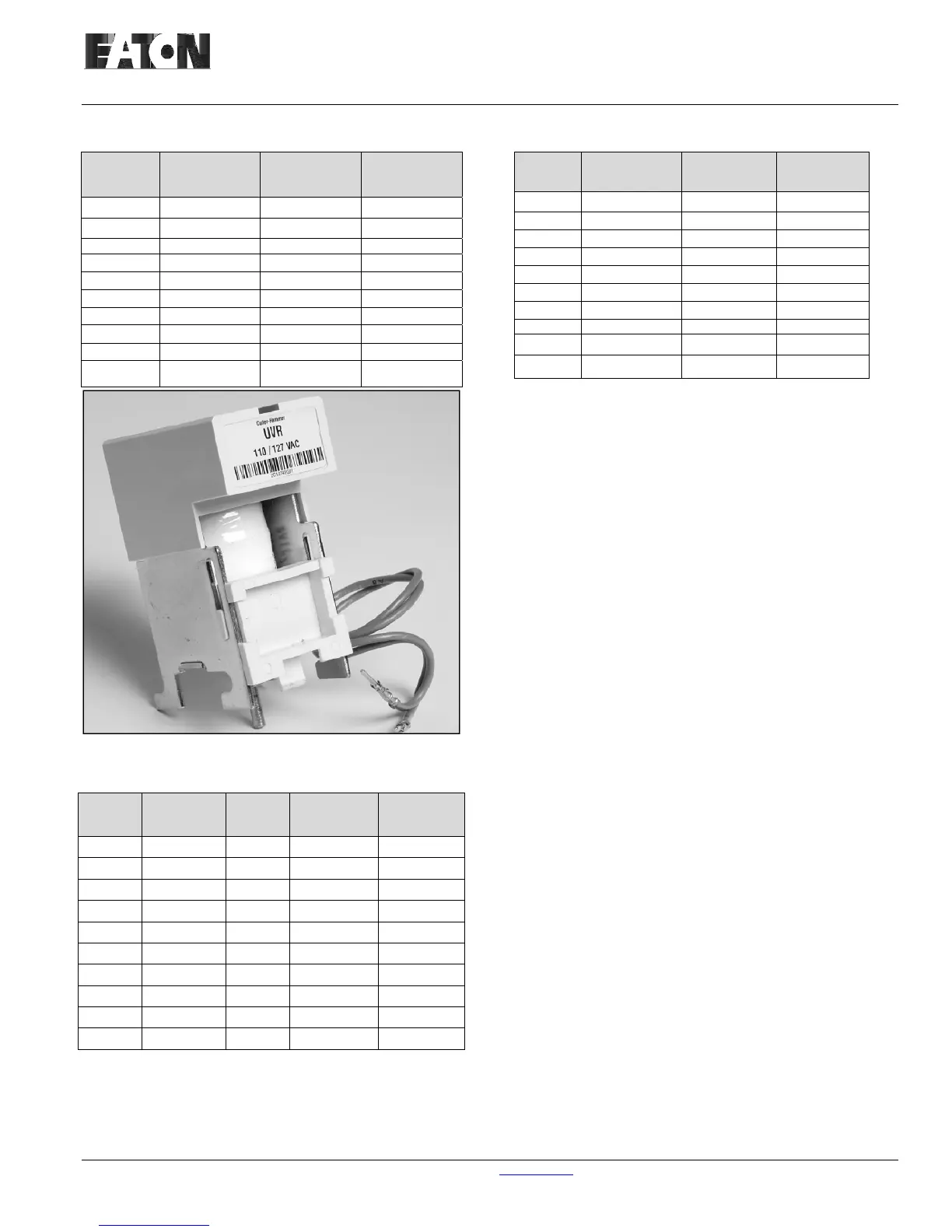
Figure 5-24 Undervoltage Release Device
Table 5.5 Undervoltage Release Rating
Control
Voltages
Operational
Voltage
Range
Dropout
Voltage
35-60%
Inrush Power
Consumption
Continuous
Power
Consumption
24 Vdc 20 - 26 8 - 14 250 VA 18 VA
48 Vdc 41 - 53 17 - 29 275 VA 18 VA
110 Vdc 94 - 121 39 - 66 450 VA 10 VA
125 Vdc 106 - 138 44 - 75 450 VA 10 VA
220 Vdc 187 - 242 77 - 132 450 VA 10 VA
250 Vdc 213 - 275 88 - 150 450 VA 10 VA
110 Vac 94 - 121 39 - 66 450 VA 10 VA
120 Vac 102 - 132 42 - 72 450 VA 10 VA
220 Vac 187 - 242 77 - 132 400 VA 10VA
240 Vac 204 - 264 84 - 144 400 VA 10VA
Table 5.4 Spring Release Ratings
Control
Voltages
Operational
Voltage Range
Inrush Power
Consumption
Typical
Closing Time
24 Vdc 20-27 250 VA 60 ms
48 Vdc 41-53 250 VA 60 ms
110 Vdc 94 - 121 450 VA 60 ms
125 Vdc 106-138 450 VA 60 ms
220 Vdc 187 - 242 450 VA 60 ms
250 Vdc 213 - 275 450 VA 60 ms
110 Vac 94 - 121 450 VA 60 ms
120 Vac
102 -
132
450 VA 60 ms
220 Vac 187 - 242 450 VA 60 ms
240 Vac 204 - 264 450 VA 60 ms
5-6.2 INTERNAL ELECTRICAL ACCESSORIES
Other electrical accessories are mounted inside the
circuit breaker behind the front cover. Access to these
devices is gained by simply removing the front cover.
There are three internally mounted electrical
accessories:
Motor Operator
Auxiliary Switch
Trip Indicator/Overcurrent Trip Switch
Motor Operator - A motor operator is a rugged electric
motor assembly internally mounted in the circuit
breaker (Figure 5-25 and Table 5.6). It charges the
closing springs electrically for remote or local
operation. The motor operator can be factory or field
installed.
Manually operated circuit breakers are pre-wired to
accept the addition of an electrical motor operator in the
field. A UL listed motor operator kit is available for this
conversion.
Auxiliary Switch - A 5a, 5b auxiliary switch is
supplied as standard on all circuit breakers for
customer use (Figure 5-26 and Table 5.7). The switch
is a heavy duty, double break type switch with wipe
type contacts.
Trip Indicator/Overcurrent Trip Switch - The
optional trip indicator is supplied on breakers ordered
with Digitrip RMS trip units. It provides a visual
indication, through a red pop-out plunger mounted
above the trip unit, that the electronic trip system has
initiated a trip signal. The trip indicator is reset by
pushing the plunger back into its normal position. The
trip indicator does not have to be reset in order to
operate the breaker or the trip unit.
The trip indicator is available with or without a SPST
overcurrent trip switch. This switch only changes
state with the trip indicator.
 Loading...