6
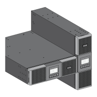
3 System Description
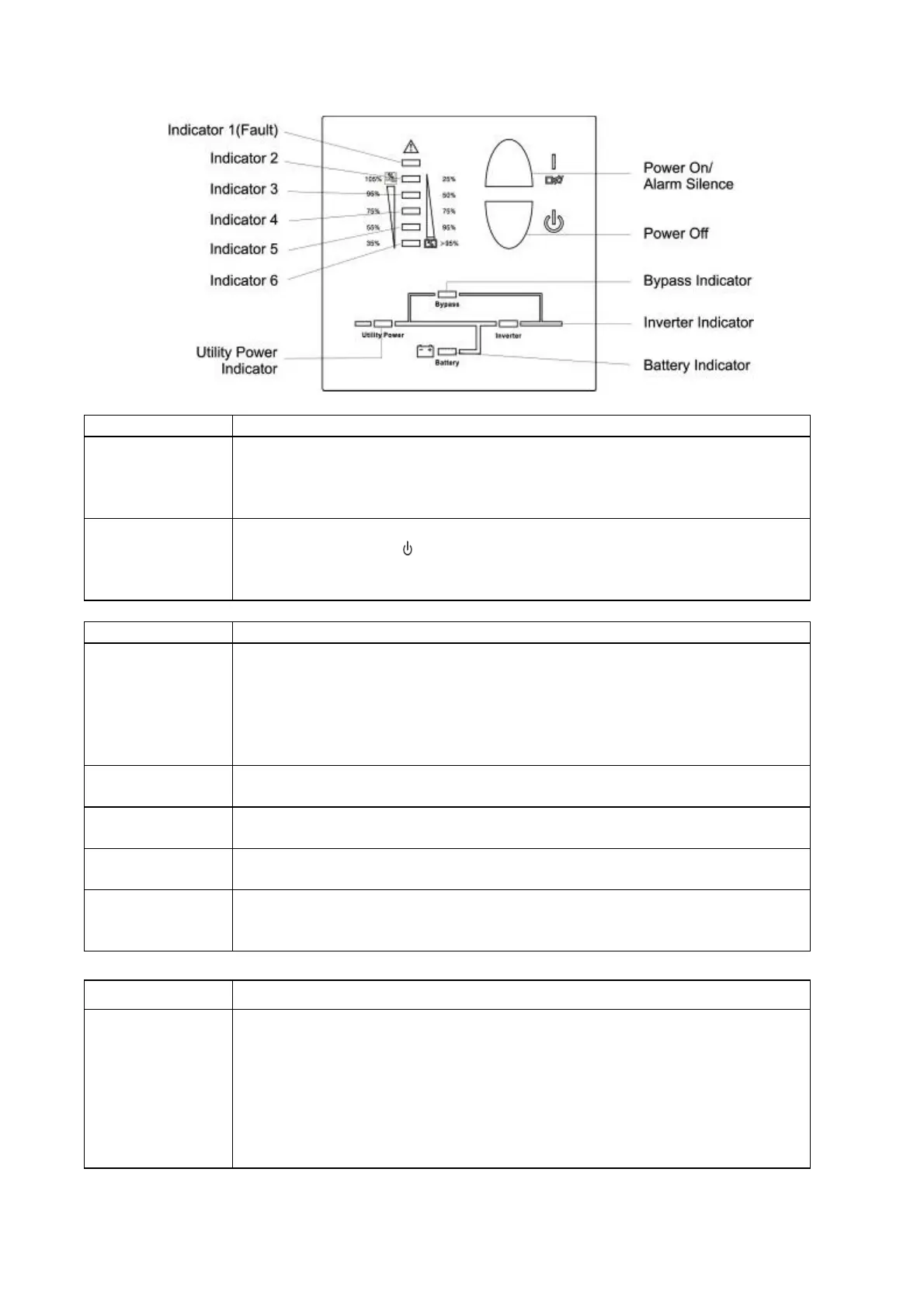
Switch Function
ON – Switch
1)Turn on UPS system:
By pressing the ON-Switch “I” the UPS system will be turned on.
2)Deactivate audible alarm:
By pressing this switch an audible alarm can be deactivated.
OFF-Switch
When mains power is normal, the UPS system switches to Standby mode by
pressing OFF-Switch “
“. It is then switched to Bypass and the inverter is off.
At this moment, the output sockets are supplied with voltage via the bypass if
the mains power is available.
Display Function
Utility Power
LED
The green Utility Power LED lights up if mains voltage is applied to the UPS
input.
Utility Power LED blinks when the phase and neutral conductor are reversed
in the input of the UPS system.
If Utility Power LED and BATTERY LED light up, the mains power supply is out
of tolerance.
BATTERY LED
The orange BATTERY LED lights up when the mains power is failed and the
inverter is being powered by the batteries.
BYPASS LED
The orange BYPASS LED lights up indicating that the load is directly
connected to the mains supply via the bypass.
INVERTER LED
The green INVERTER LED lights up indicating that the load is connected to
the inverter output.
FAULT LED
The red FAULT LED lights up and a continuous audible alarm can be heard
indicating that the UPS system is in fault condition. Press the Standby switch
in order to turn off the alarm.
Display Function
Load and battery
capacity LEDs
These LEDs show the load of the UPS system if the mains power is available
(normal operation):
2nd LED: 96%-105% 3rd LED: 76%-95% 4th LED: 56%-75%
5th LED: 36%-55% 6th LED: 0-35%
In the battery operation, the LEDs indicate the capacity of the batteries:
2nd LED: 0-25 % 3rd LED: 26%-50 % 4th LED: 51%-75 %
5th LED: 76%-95 % 6th LED: 96%-100 %
 Loading...