WALL-MOUNTED BYPASS SWITCH INSTALLATION
Eaton 9155 UPS (8–15 kVA) User's Guide S 164201553 Rev G (www.eaton.com/powerquality)
39
9. Install conduit and connect the wiring from the bypass switch to the UPS
terminal block.
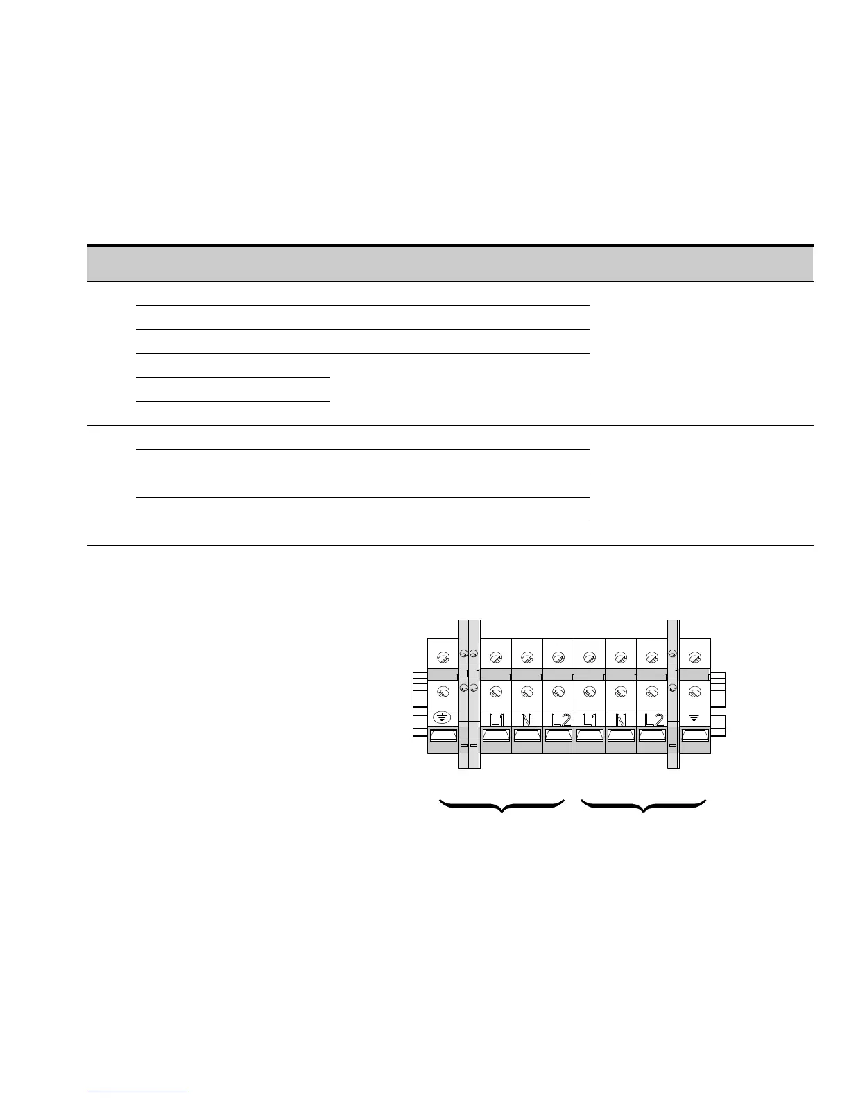
See Table 5 for specifications and Figure 27 for a detailed view of the UPS
terminal block.
Table 5. UPS Terminal Block (TB1) Wiring
Wire Function Terminal Position
Input Circuit Breaker
Rating
Minimum Wire Size*
Tightening
Torque
Conduit Connection
(Entry Size)
Input
Ground TB1‐1 8 AWG
25 lb in
(2.83 Nm)
2” access hole for
1‐1/2” conduit
AUX TB1‐2-1 and 2-2 —
Not Used TB1‐2A-1 and 2A-2 —
L1 TB1‐3
8 kVA
10 kVA
12 kVA
15 kVA
60A
80A
100A
100A
4 AWG (21.2 mm
2
)
3 AWG (26.7 mm
2
)
2 AWG (33.6 mm
2
)
2 AWG (33.6 mm
2
)
Neutral TB1‐4
L2 TB1‐5
Output
L1 TB1‐6 8 AWG
25 lb in
(2.83 Nm)
2” access hole for
1‐1/2” conduit
Neutral TB1‐7 8 AWG
L2 TB1‐8 8 AWG
Not Used TB1‐8A-1 and 8A-2 —
Ground TB1‐9 8 AWG
* Use only 75°C-rated copper wire. Minimum wire size is based on 120/208 full load ratings applied to NEC Code Table 310‐16. Code may require a larger
AWG size than shown in this table because of temperature, number of conductors in the conduit, or long service runs. Follow local requirements.
13456789
Input
TB1
22A
8A
Output
Figure 27. UPS Terminal Block
 Loading...