94 Eaton 9395XC UPS 1200kW/1200kVA, 1350kW/1350kVA or 1500kW/1500kVA 164001079—Rev 01
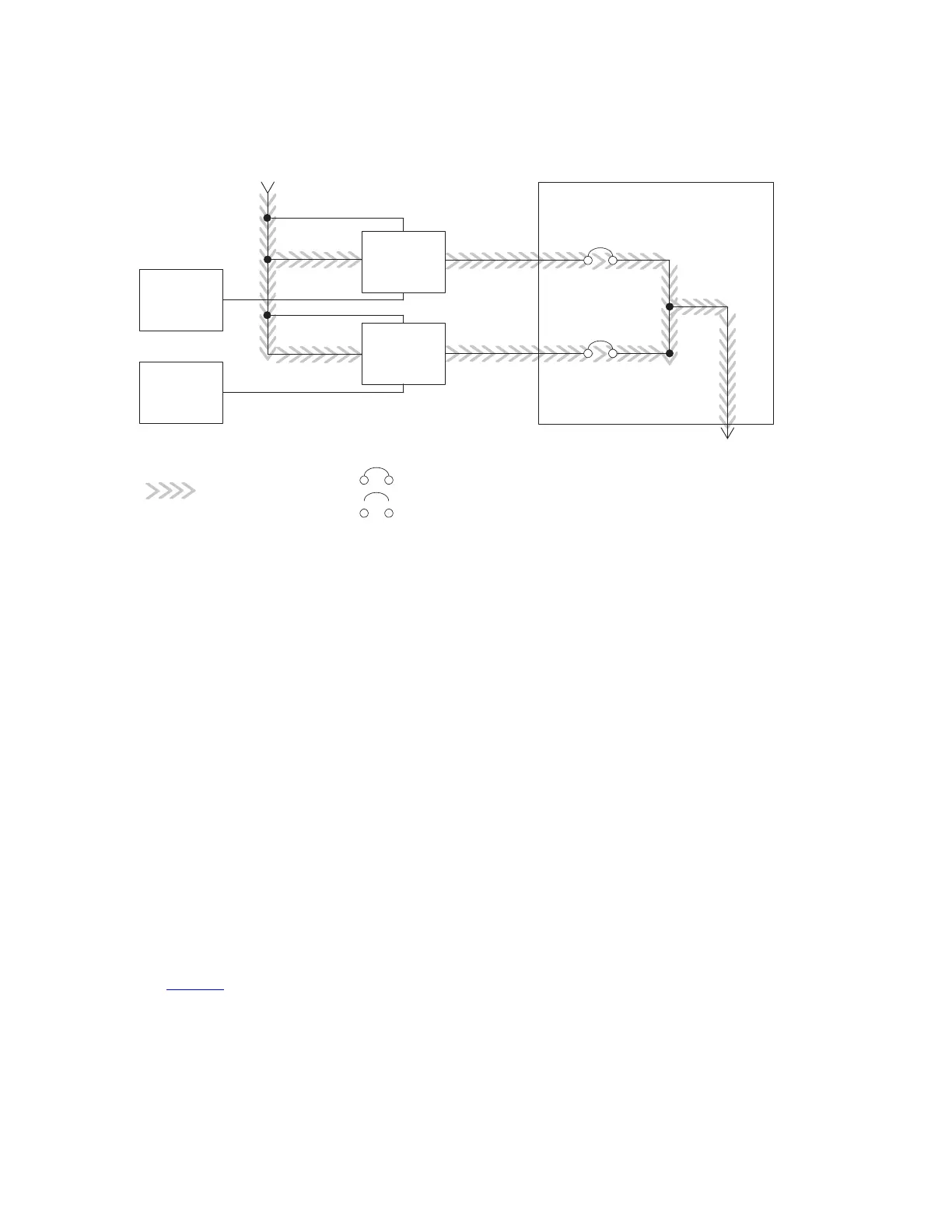
Figure 52. Path of Current through the UPSs in Bypass Mode – Distributed Bypass
Main Power Flow
UPS 1
UPS 2
Output to
Critical Load
Battery
Tie Cabinet
UPS 1 Output
Bypass Input
UPS 2 Output
Battery
Closed
Open
Breakers
The distributed bypass system can be transferred from Normal mode to Bypass mode manually. However, the
distributed bypass system automatically switches to Bypass mode whenever the UPSs can no longer supply
the critical load. If the distributed bypass system transfers to Bypass mode from Normal mode due to an output
voltage deviation, the distributed bypass system automatically attempts to return to Normal mode (up to three
times within a 10-minute period). After three transfer attempts or an overload, the system locks the critical load
to the bypass source and requires operator intervention to transfer.
Bypass mode is a normal operating mode, not an alarm condition. However, if the distributed bypass system is
unable to return to Normal mode following an automatic transfer to Bypass mode, an alarm condition is
recorded.
Bypass may also be used when the UPSs or UPMs in the system must be shut down to perform routine
maintenance or repairs.
In the Parallel Redundant (N+1) arrangement, the bypass circuitry in each UPS operates to support the applied
loads on bypass. If the UPSs are online and one UPS trips offline, the remaining UPSs do not go to bypass as
long as they have the capacity to support the load.
In the Parallel Capacity (N+0) arrangement, if one UPS trips offline and goes to bypass, the remaining UPSs
also go to bypass.
66..44..44 BBaatttteerryy MMooddee DDiissttrriibbuutteedd BByyppaassss
The UPSs transfer to Battery mode automatically if a utility power outage occurs, or if the utility power does not
conform to specified parameters. In Battery mode, the battery provides emergency DC power that the inverter
converts to AC power.
Figure 53 shows the path of electrical power through the distributed bypass system when operating in Battery
mode.
While in Battery mode, the UPSs sound an audible horn, illuminate a visual indicator lamp on the front panel
(Online and On Battery), and create an entry into the alarm event history. As the battery discharges, the boost
converter and inverter constantly make minute adjustments maintaining a steady output. The UPSs remain in
Understanding UPS Operation
 Loading...