80 Eaton 9395XC UPS 1200kW/1200kVA, 1350kW/1350kVA or 1500kW/1500kVA 164001079—Rev 01
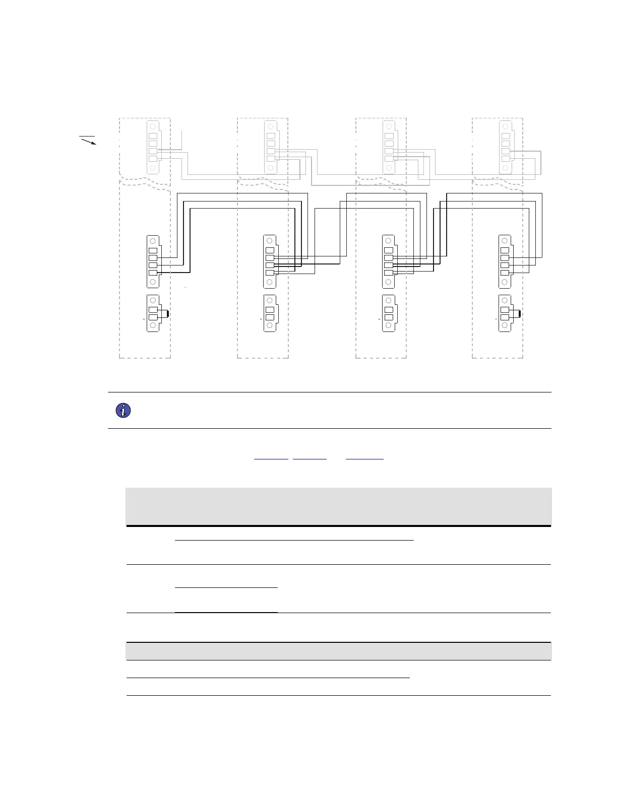
Figure 43. Distributed Bypass System CAN Interface Wiring
GND-E
CANBL
GND-ISO
CAN-BH
CANBL
CANBL 1
CANBL
CANBL 1
CANBL
CANBL 1
UPS 1
CAN15
CAN13
J19
REMOTE EPO NO
PULL CHAIN
PULL CHAIN/REM EPO RTN
REMOTE EPO NC
Remote EPO
Return (shared terminal)
NOTE:
Pull Chain wiring shown in this
gure only applicable to UPS
congurations without MOBs.
Reference only.
UPS 2
GND-E
*CANBL
*GND-ISO
*CAN-BH
UPS 3
(If installed)
GND-E
*CANBL
*GND-ISO
*CAN-BH
CANBL
CANBL 1
UPS 4
(If installed)
GND-E
CANBL
GND-ISO
CAN-BH
*
Double-wire terminations in connectors from
UPS 2 and/or UPS 3 (if installed).
REMOTE EPO NO
*PULL CHAIN
*PULL CHAIN/REM EPO RTN
REMOTE EPO NC
REMOTE EPO NO
*PULL CHAIN
*PULL CHAIN/REM EPO RTN
REMOTE EPO NC
REMOTE EPO NO
PULL CHAIN
PULL CHAIN/REM EPO RTN
REMOTE EPO NC
NOTE 1 External CAN connections between UPS cabinets require shielded twisted pair wires.
NOTE 2 Always confirm contact operation prior to wiring.
5. Route and install distributed bypass system pull-chain wiring between the UPS cabinets and customer-
supplied tie cabinet MOBs. See Table 20, Table 21 and Figure 44 for wiring information.
Table 20. External Pull Chain with MOBs Connections
Terminal Terminal # Name
Description
Recommended Wire Size
Max/Min
[Recommended]
J19
3
Pull Chain Backup Control for parallel operation.
Max Wire = 14AWG / Min Wire =
30AWG
4
Pull Chain/
EPO RTN
Shared RTN for PULL CHAIN and
REMOTE EPO functions.
CN5
1
BLD ALRM 5
RTN
Input: Programmable UPS alarm,
activated by a remote dry contact
closure. Default function set for on
maintenance bypass.
Max Wire = 14AWG / Min Wire =
30AWG]
[Recommended Wire: Twisted Pair
Wires #18AWG (per Building Alarm)]
2
BLD ALRM 5
Table 21. Pull-Chain Wiring Terminations with MOBs
From
To Function
UPS 1 CN5 – BLD ALARM 5 RTN
MOB 1 AUX 1 COM
MOB Open Alarm
UPS 1 CN5 – BLD ALARM 5
MOB 1 AUX 1 NC
Installing Options and Accessories
 Loading...