55..66..22 BBaatttteerryy bbrreeaakkeerr wwiirriinngg iinntteerrffaaccee
When the original accessory battery cabinet from the manufacturer is used, the battery breaker interface
wiring is provided with the cabinet. The wiring is connected to the X8 terminal in the UPS.
When a third-party battery system is used, the breaker must be equipped with auxiliary signal and should
have a 24 Vdc shunt trip for remote opening of the breaker, when needed.
See Section
5.3.1 Battery trip wiring for installation instructions.
55..66..33 RReellaayy oouuttppuutt iinntteerrffaaccee ccoonnnneeccttiioonnss
The general alarm relay is a dry relay signal output. The relay can be used for informing the operators
about UPS alarm conditions, for example through a building management system. By default, the relay is
configured to activate when the UPS general alarm is active, that is, any event when the ALARM status is
active. The relay can also be configured to activate by some other event, but this needs to be done by
authorized service personnel.
Additional relay outputs are available with mini-slot cards. Relay outputs can be configured to be activated
by various events. Configuration can be done by an authorized Eaton Customer Service Engineer or by
other qualified service personnel authorized by Eaton.
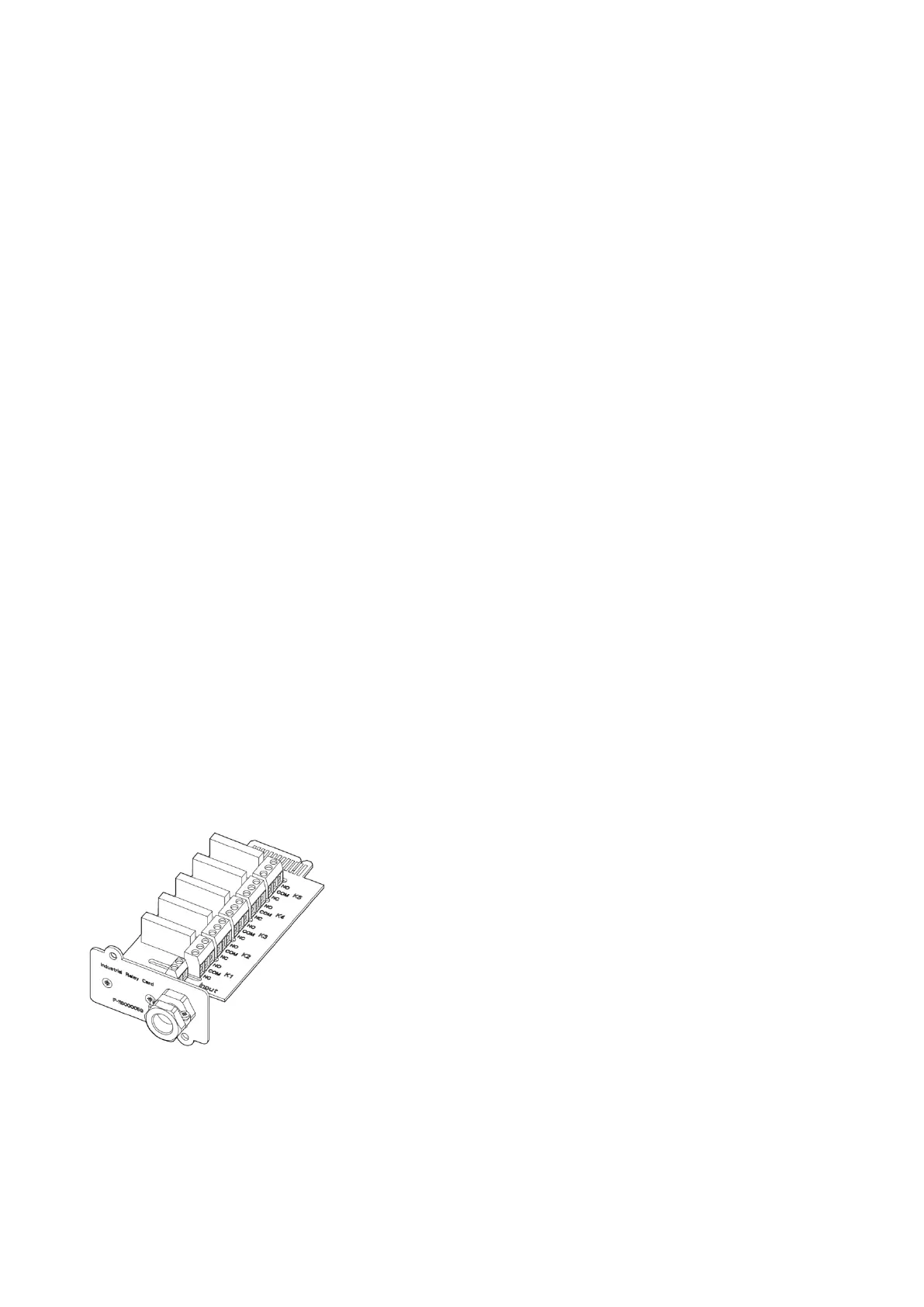
55..66..44 IInndduussttrriiaall RReellaayy CCaarrdd iinntteerrffaaccee ccoonnnneeccttiioonnss
Relays K1 through K5 are identical in function. Each output contact function can be assigned by the user.
The UPS information may also be configurable.
To install the industrial relay card (INDRELAY-MS):
1. Make sure that the ancillary equipment system is turned off and all the power sources are removed.
Refer to the appropriate operation manual of any ancillary equipment for shutdown instructions.
2. Install wiring from the card to the monitoring equipment using appropriate cable with double insulation
through the cable exit opening in the card.
3. Connect wiring between the card’s terminal blocks and the monitoring equipment using terminations.
Connect one wire to COM (Common) and another to either NC or NO to select the Normally Open or
Normally Closed option.
4. Install the card into an open MiniSlot communication bay in the UPS cabinet.
Figure 21. Industrial Relay Card
EATON 93PM G2 UPS USER’S AND INSTALLATION GUIDE P-164000956
-
February 2021 www.eaton.eu 5544
 Loading...