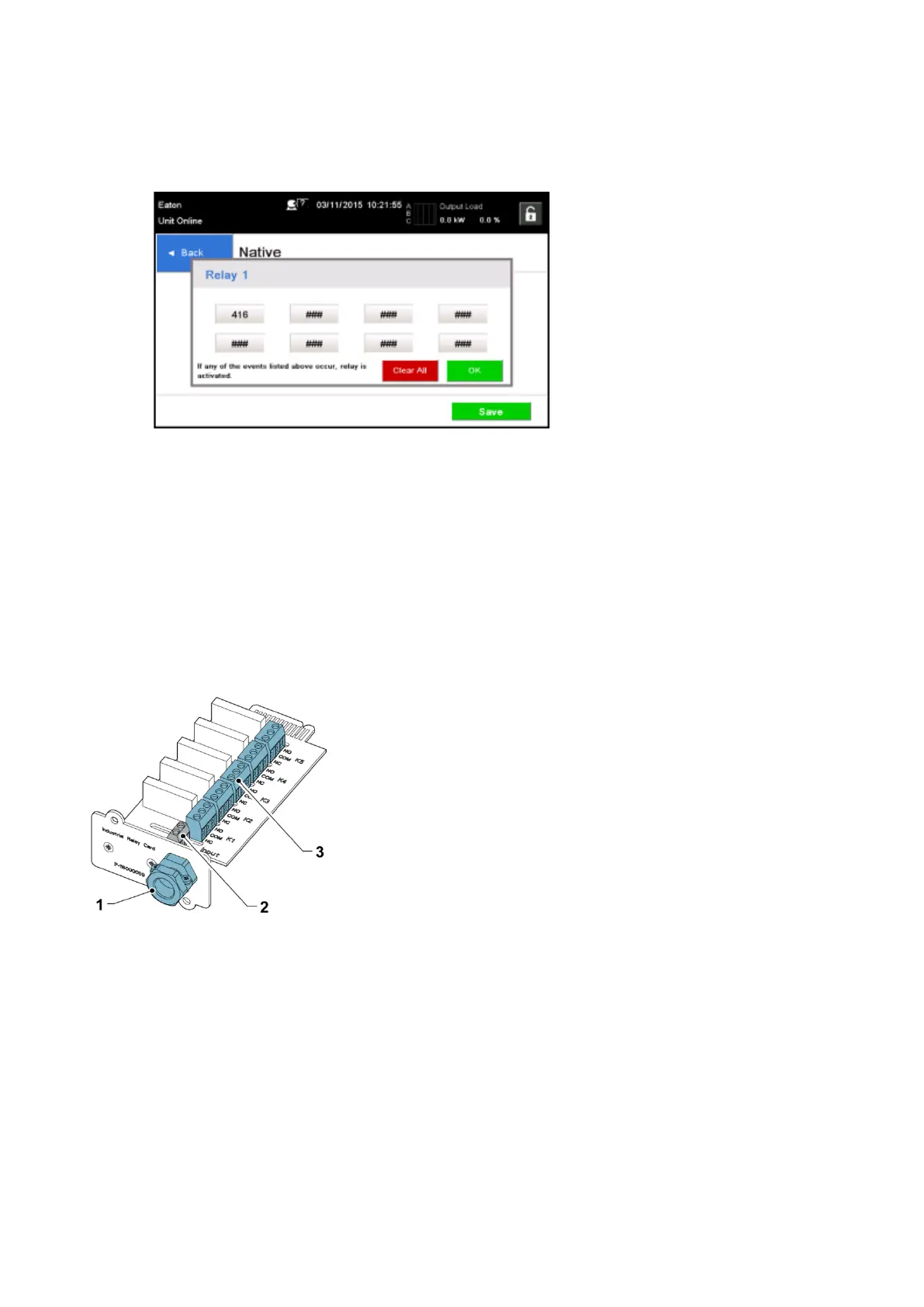
8. Press OK and Save to save the changes.
Figure 37. Entering the codes of the functions that will trigger the relay
9. If you selected one of the MiniSlots, the following default values are available:
• Relay 1: #262 On Line (LED is lit)
• Relay 2: #260 On Battery (LED is lit)
• Relay 3: #352 Alarm (LED is lit)
• Relay 4: #261 On Bypass (LED is lit)
• Relay 5: #15 Low Battery warning
Alternatively, you can configure the relays with any event you want.
10. You can test the relays by selecting any of the options in the test mode (see Figure
36: Options for
relay outputs configuration).
Figure 38. Relays
1. Cable exit opening for up to 12 mm
(½”) conduit
2. Signal input connector with voltage
supply
3. K1 thru K5 terminal connections
for relay contacts to operator's
monitoring equipment
EATON 93PM G2 UPS USER’S AND INSTALLATION GUIDE P-164000956
-
February 2021 www.eaton.eu 6677
 Loading...