Page 32
8-11kVA EU_EN
6. Communication
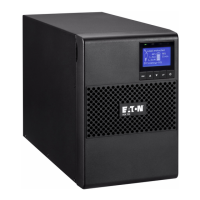
Remote control connection and test
1 - Check the UPS is shut down and the electrical supply network disconnected.
2 - Remove RPO connector from the UPS by unfitting the screws.
3 - Connect a normally closed volt-free contact between the two pins of connector.
13
Normally closed
Contact open: shut down of UPS
To return to normal operation, deactivate the external remote shut down
contact and restart the UPS from the front panel.
4 - Plug the RPO connector into the back of the UPS and fix the screws.
5 - Connect and restart the UPS according to the previously described procedures.
6 - Activate the external remote shut down contact to test the function.
Always test the RPO function before applying your critical load to avoid accidental load loss.
z Connectivity Cards
Connectivity cards allow the UPS to communicate in a variety of networking environments and with
different types of devices. The 9SX and 9PX models have one available communication bay for the
following
connectivity cards:
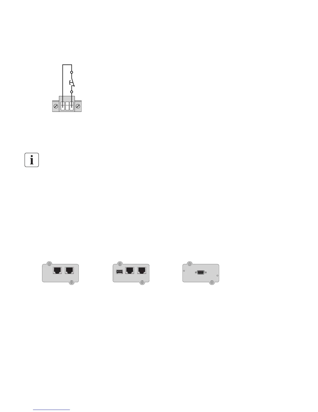
Network-MS card z - has SNMP and HTTP capabilities as well as monitoring through a Web
browser interface; connects to Ethernet network. In addition, a Environmental Monitoring Probe
can be attached to obtain humidity, temperature, smoke alarm, and security information.
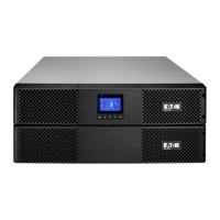
Modbus-MS card z - has connection to Modbus protocol in addition to network management.
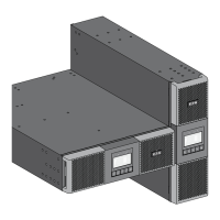
Relay-MS card z - has isolated dry contact (Form-C) relay outputs for UPS status: Utility failure,
Battery low, UPS alarm/OK, or on Bypass.
See on page 21 for the location of the communication bay.
Relay-MS cardNetwork-MS card
ETHERNET
100M 10 M UPS data Reset
Setting/Sensor
Modbus-MS card
ETHERNET
100M 10 M UPS data Reset
Setting/Sensor
 Loading...