- 9 -
AC power supply
Incandescent light (resistive load)
Manually exclusive output: Uses external circuit and forms an interlock, together
with the ELC internal program, to ensure safety protection in case of any
unexpected errors.
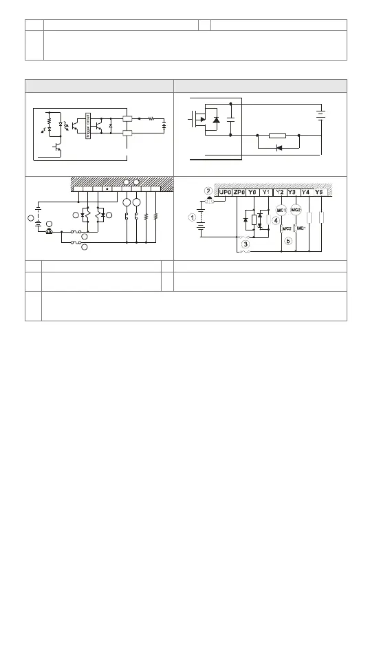
Transistor (NPN & PNP) Contact Circuit Wiring
Transistor output (NPN) Transistor output (PNP)
Y0
LED
C0
TRANSISTOR OUTPUT
LOAD
< 0. 5A
VDC
+
D
Y
UP
ZP
Sma ll er power
D: 1N4 00 1 d iode or eq ui val ent comp onent
MC1
MC2
2
3
1
C0 Y0 Y1 C4 Y10 Y11 Y12 Y13
5
4
5
3
4
DC power supply
Emergency stop
Circuit protection fuse
Flywheel diode (SB360 3A 60V) + inductive
load
Manually exclusive output: Uses external circuit and forms an interlock, together
with the ELC internal program, to ensure safety protection in case of any
unexpected errors.
Trial Run
Preparation
1. Prior to applying power, please verify that the power lines and the input/output
wiring are correct. And be advised not to supply 110V AC or 220V AC into the I/O
terminals, or it might short-circuit the wiring and would cause direct damage to the
ELC.
2. After using the peripheral devices to write the program into the ELC and that the
ERROR LED of the ELC is not on, it means that the program in use is legitimate,
and it is now waiting for the user to give the RUN command.
3. Use ELC-HHP to execute the forced On/Off test of the output contact.
Operation & Test
1. If the ERROR indicator does not flash, you can use the RUN/STOP switch or a
peripheral device (ELC-HHP or ELCSoft) to give a RUN instruction. The RUN
indicator should be continuously on at this time. That the RUN indicator does not
flash indicates ELC has no program in it.
2. When ELC is in operation, use ELC-HHP or ELCSoft to monitor the set value or
temporarily saved value in timer (T), counter (C), and register (D) and force On/Off
of output contacts. That the ERROR indicator is on (not flashes) indicates that part
of the program exceeds the preset time-out. In this case, you have to set the
RUN/STOP switch as STOP first, check special register D1008 and obtain the
location in the program where time-out takes place. Please refer to the WDT
instruction to solve this problem.
Operation of ELC Basic Sequential Instructions &
Application Instructions
1. The basic sequential instructions and application instructions of ELC-PV/ELC2-PV
series are compatible with all ELC series ELCs. See Eaton “ELC System Manual”
for relevant information.
2. All ELC series ELCs are compatible with ELC-HHP handheld programming panel,
 Loading...


