- 6 -
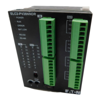
#1: Life curves
Model Name & I/O Configuration
Standard functional ELC
Input Output I/O configuration
Model Power
Point Type Point Type Relay
Transistor
(NPN)
Transistor
(PNP)
ELC-PV28NNDR
ELC2-PV28NNDR
Relay
ELC-PV28NNDT
ELC2-PV28NNDT
Transistor
(NPN)
ELC2-PV28NNDP
24VDC
16
DC
(Sink
or
source)
12
Transistor
(PNP)
S/S
X0
X1
X2
X3
X4
X5
X6
X7
S/S
X10
X11
X12
X13
X15
X16
X17
C0
Y0
Y1
Y2
Y3
Y4
Y5
Y6
Y7
Y10
Y11
Y12
Y13
C1
C2
C3X14
S/S
X0
X1
X2
X3
X4
X5
X6
X7
S/S
X10
X11
X12
X13
X15
X16
X17
C0
Y0
Y1
C1
C2
Y4
Y5
Y6
Y7
Y12
Y13
C3
Y2
Y3
C4
Y10
Y11
X14
S/S
X0
X1
X2
X3
X4
X5
X6
X7
S/S
X10
X11
X12
X13
X15
X16
X17
UP0
ZP0
Y0
Y1
Y4
Y5
Y6
Y12
Y13
Y7
Y2
Y3
Y10
Y11
X14
UP1
ZP1
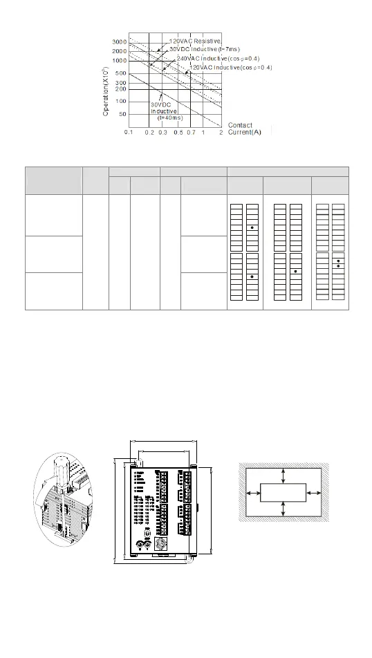
Installation & Wiring
Mounting & Wiring
The ELC/ELC2 can be secured to a cabinet by using the DIN rail of 35mm in height and
7.5mm in depth. When mounting ELC/ELC2 to DIN rail, be sure to use the end bracket
to stop any side-to-side movement of ELC/ELC2 and reduce the chance of wires being
loose. A small retaining clip is at the bottom of ELC/ELC2. To secure ELC/ELC2 to DIN
rail, place the clip onto the rail and gently push it up. To remove it, pull the retaining clip
down and gently remove ELC/ELC2 from DIN rail, as shown in figure 1.
Please use M4 screw (see figure 2) according to the dimension of the product. Please
install ELC/ELC2 in an enclosure with sufficient space around it to allow heat dissipation
(see figure 3).
90
53.2
70
101
109.4
MPU
D
D
D
D>50mm
Figure 1 Figure 2 (Unit: mm) Figure 3
 Loading...


