- 1 -
The ELC-PV/ELC2-PV series includes five 28-point (16 inputs + 12 outputs) controllers.
An ELC-PV/ELC2-PV series provides various instructions, and the size of the program
memory in it is 16K steps. It is able to connect to all ELC series extension modules,
including digital input/output (max. 224 I/O points), analog modules (A/D, D/A
transformation and temperature units) and all kinds of new high-speed extension
modules. Four groups of high-speed (200KHz) pulse outputs, and two new 2-axis
interpolation instructions are included. ELC-PV/ELC2-PV series controllers are small in
size and, and can be installed easily..
EN ELC-PV/ELC2-PV is an OPEN-TYPE device. It should be installed in a control
cabinet free of airborne dust, humidity, electric shock and vibration. To prevent
non-maintenance staff from operating ELC-PV/ELC2-PV, or to prevent an
accident from damaging ELC-PV/ELC2-PV, the control cabinet in which
ELC-PV/ELC2-PV is installed should be equipped with a safeguard. For example,
the control cabinet in which ELC-PV/ELC2-PV is installed shall require a tool or
key to be opened.
EN DO NOT connect AC power to any of I/O terminals, otherwise serious damage
may occur. Please check all wiring again before ELC-PV/ELC2-PV is powered up.
After ELC-PV/ELC2-PV is disconnected, Do NOT touch any terminals in a minute.
Make sure that the ground terminal
on ELC-PV/ELC2-PV is correctly
grounded in order to prevent electromagnetic interference.
FR ELC-PV/ELC2-PV est un module OUVERT. Il doit être installé que dans une
enceinte protectrice (boitier, armoire, etc.) saine, dépourvue de poussière,
d’humidité, de vibrations et hors d’atteinte des chocs électriques. La protection
doit éviter que les personnes non habilitées à la maintenance puissent accéder à
l’appareil (par exemple, une clé ou un outil doivent être nécessaire pour ouvrir a
protection).
FR Ne pas appliquer la tension secteur sur les bornes d’entrées/Sorties, ou l’appareil
ELC-PV/ELC2-PV pourra être endommagé. Merci de vérifier encore une fois le
câblage avant la mise sous tension du ELC-PV/ELC2-PV. Lors de la
déconnection de l’appareil, ne pas toucher les connecteurs dans la minute
suivante. Vérifier que la terre est bien reliée au connecteur de terre afin d’éviter
toute interférence électromagnétique.
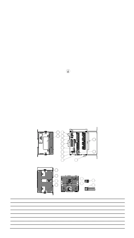
Product Profile & Outline
1
2
3
4
5
6
7
14
10
9
8
13
12
11
70
3903
17
18
16
15
60
20
19
21
Unit: mm
1 Status indicators of POWER, RUN, BAT.LOW and ERROR
2 COM1(RS-232) (Rx) indicator
3 COM2(RS-485) (Tx) indicator
4 I/O point indicators
5 RUN/STOP switch
6 VR0: Start-up by M1178/D1178 corresponding value
7 VR1: Start-up by M1179/D1179 corresponding value
8 I/O terminal
 Loading...


